1-Visitor
March 10, 2014
Solved

Feature Failure with Repeating Patterns

  • March 10, 2014
  • 6 replies
  • 31495 views

Just recently I transfered from one division of my company to another. The first division used SolidWorks and the new division uses Creo. It has been over a decade since I used Pro/E so I am effectively a newbie. I am trying to create a structure based on a 3D array of a unit cell. Here is a screen shot of a portion of the cell created in Creo.
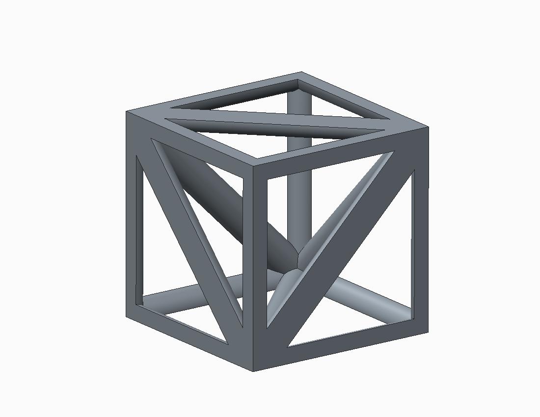
truss-pyramid+3.jpg

This is where I get stuck. This part must be mirrored a few times to create the actual unit cell. Since the mirror feature in Creo has no ability to revise the selections after creating it, I am trying to figure out how to pattern it with an axial pattern. When I attempt to do so, Creo gives an error stating, "Some features failed to regenerate." See the attached model.

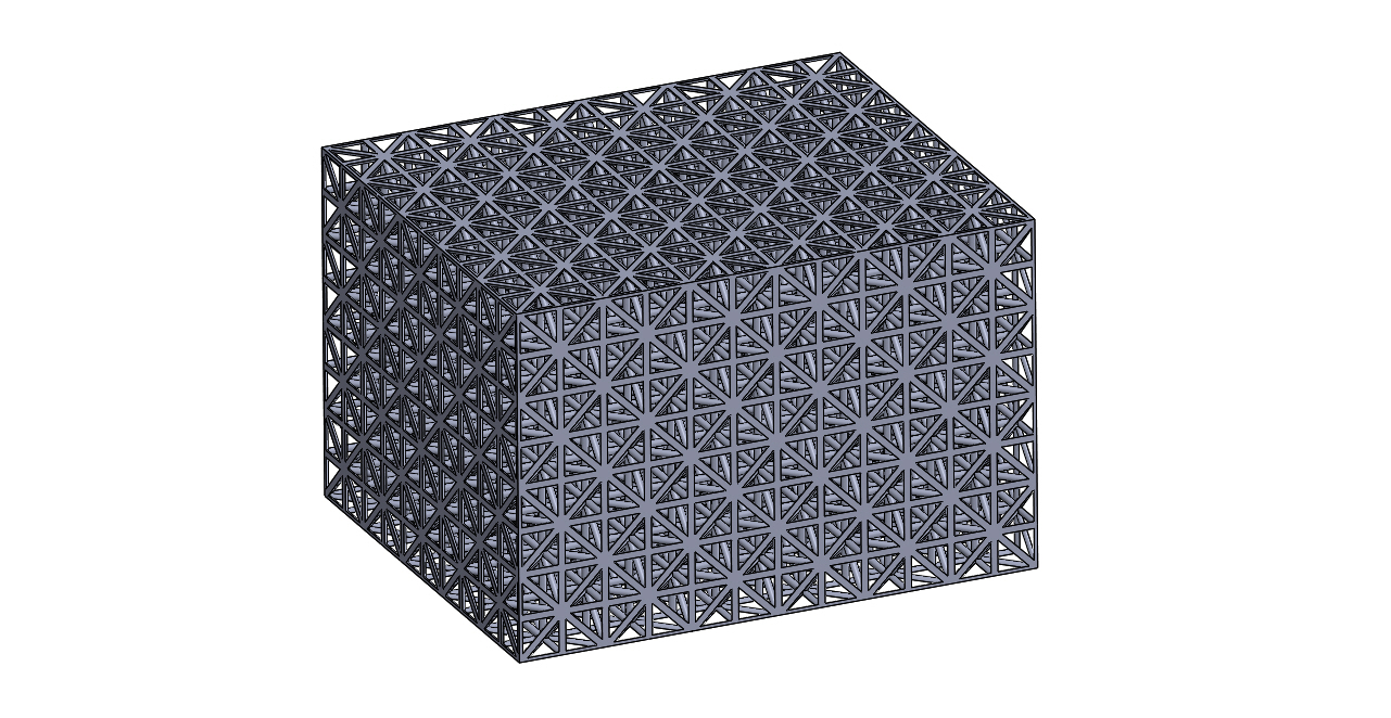
Below is a screen shot from SolidWorks showing what the unit cell should look like, and another screen shot showing what the full 3D array should look like.
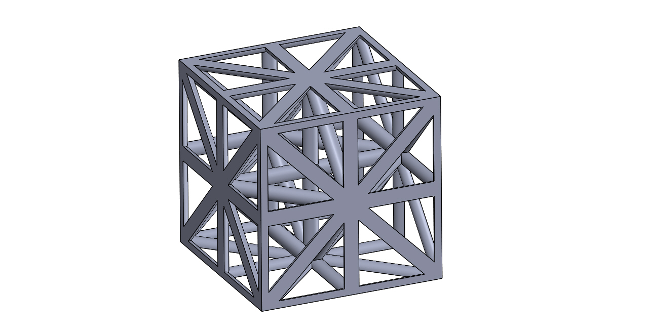
Truss+-+Pyramid+2.JPG

Truss+-+Pyramid.JPG

Any suggestions on how to make the patterns work?


This thread is inactive and closed by the PTC Community Management Team. If you would like to provide a reply and re-open this thread, please notify the moderator and reference the thread. You may also use "Start a topic" button to ask a new question. Please be sure to include what version of the PTC product you are using so another community member knowledgeable about your version may be able to assist.
Best answer by TomD.inPDX

At least I learned a few things after a day's effort to understand the fact that Creo simply doesn't do "dumb solids".

Therefore, nesting cells of a feature in a part file is not really recommended although it would be interesting to see what customer support would do with this type of requirement.

Therefore, yes, if you needed this kind of structure, it is best done in an assembly just to manage CPU and memory if nothing else.

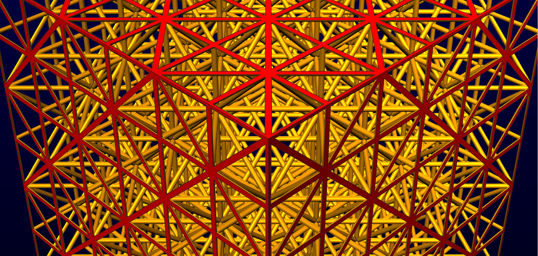
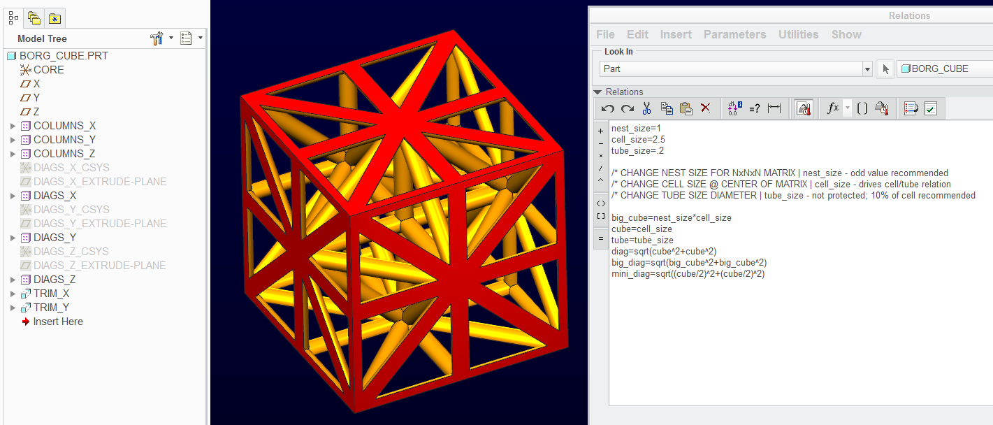
However, I did go Matt's route on this and hyped it up a little. There is an interesting patterning tip hidden in the attached file. A little trick that allowed the file to be fully parametric based on the maximum matrix size you need without any serious math to vary the patterns. 2 final trim features can size it up to odd matrices so the idea is that you can specify the cell size, the tube size, and the NxNxN matrix size (all N's being equal). Careful though... it is a CPU workout when you start going over about 5 for matrix size.

I left the attached example in a small state to minimize the file size. Just play with the 3 relations at the part level. The cube will expand form the center.

If you want the "Union Jack" to show up at the edges, use an odd value for the matrix "nest_size". The very center will always be a complete cell as outlined in the original post. A 2x2x2 matrix will grow from the center and therefore the outer cells will be divided in half all around the core cell. To avoid this, set the nest_size to 3 and trim away the extra bits.

borg_cube_II.PNG

And the glamour shot...

borg_cube.PNG

Enjoy!

6 replies

17-Peridot
March 10, 2014

The typical response from customer support for such attempts is to group the features before patterning.

I might also suggest you make sure you are on Creo 2.0 release M090. There were some serious bugs related to patterns in earlier releases. If that is not an option, you might try some other methods to create the 1st structure. Most often it is a very innocent little constraint that causes patterns to fail.

I also find that assembly patterns are a little more robust.

I will have a look at your file and see if I can find the problem area.

17-Peridot
March 10, 2014

Try using the Copy and Paste Special and use the transformation option instead of the patterns.

14-Alexandrite
March 10, 2014

I used assembly pattern to get this, so kind of cheating and it's not all one part. I did make the one cube in part mode, though with pattern and mirror, but I don't really like it. Also I think it depends on how parametric you want this in the long run.

truss.JPG

17-Peridot
March 10, 2014

Yes, I am running into the same problems. I got it to "duplicate" with the copy/paste option, which is still parametric. But the replication in general should be -much- simpler and more reliable.

BTW: How do you get a 3 dimensional pattern to work in one shot? Or can you only do this with an X-Y pattern and then a Z pattern?

14-Alexandrite
March 10, 2014

yes 2 patterns, not one shot.

This is the single cube.

I do have a completely different idea I want to try, though.

singlecube.JPG

Patriot_1776
22-Sapphire II
March 13, 2014

Looks to me like you could pattern the cube 4 times @ 90 deg around a vertical axis, say, the back left edge, then pattern the new pattern of 4 about a horizontal axis 2 @ 180 deg. Then pattern that into your block. That way you don't have to deal with those maddening mirror issues, and have full adjustability.

Patriot_1776
22-Sapphire II
March 31, 2014

Wow, there sure seems to be some buggy behavior in there. I tried a coupe things and at first I thought the external cut i used to trim the truss diameter was causing issues, and it was, so I fixed that to not use any cuts on the outside. The first 2 mirrors worked fine, so I got the bottom 4, tried to mirror that and it bombed, with a couple features in the group failing. The pattern worked a little better, but still a few non-regenerated features.

What Pro/E SHOULD do is simply mirror the GEOMETRY, and not need all the baggage of copying all the internal sketches, etc.

Got a few tricks still.

17-Peridot
March 31, 2014

You mean copy the geometry as dumb features like most others do? Yes, I agree. But solids don't work that way in Creo.

Patterns have been extremely buggy. It is suppose to be fixed as of M090 but I am willing to bet this will always be problematic. Had one blow up today that simply didn't make sense. Flipped a datum plane and all worked fine... go figure!

Patriot_1776
22-Sapphire II
April 1, 2014

Gonna try a couple tricks, such as making the original cube, copying all solid surfs, and then translating and pasting that and a solidify.

Well, at least we have a lot more tools and the ability to pattern via an axis or direction. Remember when you had to create a radial pattern by creating a radial datum thru axis on the fly, and all that nonsense. So, the interface is better, if not the code behind it.

I think Pro/E needs a total re-write to clean up the bugs, not wasted time on whiz-bang GUI's that are actually counter-productive, but maybe that's just me.........(or not)!

7-Bedrock
April 1, 2014

Hi Jeff,

My preferred solution for something like this is to make a surface copy, pattern that, then solidify.

If you repeat the feature creation you will incur a significant overhead as features need to recalculate their intersections with existing geometry as well as adding their parameters to the file.

A surface copy has minimal parameters associated with it and the intersection calculations where one feature crosses another have already been done.

After copying use the paste special to apply transformation parameters then pattern the transformed surface. A ref pattern solidify will then complete the solid part.

regards

Phil

17-Peridot
April 1, 2014

Remember though that surfaces require merging. Therefore the copies require merging to each other. That is what is taking up all that time in the solid model patterns. If you were not going to bother merging the surface quilts in the matrix pattern, you might as well make it a single solid cell and assemble them at a next level with the pattern. We already know that this is very efficient.

Philip, welcome to the forum.

Also, please do not attach in RAR format. I do not allow any rar decoding on my computer.

7-Bedrock
April 1, 2014

Here it is in zip format.

The model is solid but incurs fewer intersection calculations by solidifying the transformed quilt than patterning all the features.

To go from 3x3x3 to 9x9x9 takes 14 seconds using 2.4Gz i7 3840QM processor. This appears much quicker than some of the other quoted times.

Regards

Phil

truss.bmp

1-Visitor
April 4, 2014

Thanks for all the input and ideas on this issue. I contacted technical support and the representative I spoke with seemed to think that this is a bug. He tried the Geometry Pattern and spaced the instances 2.51 mm apart, so that they have just a little space between them. When he did so they worked fine, even though they do not work correctly when touching. He forwarded the issue on to R&D, so it will be interesting to hear their response.

In the mean time maybe one of the alternate techniques mentioned here will lead to a robust model. Then again, I might just beg a plead with management to let me model this part with SolidWorks. Some might say that SolidWorks creates patterns with dumb solids. After wrestling with Creo off and on for four weeks to create this part, those dumb solids are looking a whole lot like smart solids.

14-Alexandrite
April 4, 2014

Jeff Wickham wrote:

After wrestling with Creo off and on for four weeks to create this part, those dumb solids are looking a whole lot like smart solids.

So, what are you trying to do? Aren't there multiple solutions in this thread?

1-Visitor
April 8, 2014

By my comment I certainly did not intend to detract from the efforts people have expended on this issue. There are indeed multiple solutions in this thread, ones that are marvels of creativity and skill. I am humbled by the generous hours people have spent on this issue, and I am truly grateful.

My comment was solely directed at the software, not the users or the solutions presented here. It seems to me that Creo needs a robust way to create these patterns with only a minimum amount of time and skill. It has been amazing to watch such experienced users collaborate and come up with unique ways to tackle this part. My point is that ideally the software should contain capability so that an almost new user working alone can create these patterns in just a couple of minutes. Maybe once PTC gets the bugs fixed with the Geometry Pattern feature it will provide that sort of functionality.