13-Aquamarine
June 12, 2015
Solved

Finite friction blocks

  • June 12, 2015
  • 7 replies
  • 25294 views

Hello All,

I am trying to develop a feel for the behaviour of Creo3.0's finite friction.

So starting with a simple model


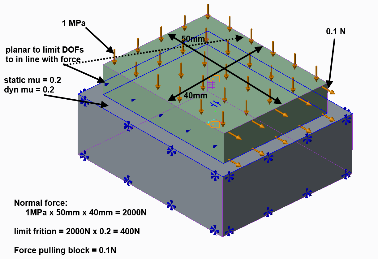
Text book concludes no sliding.

Reality tells us that the pressure distribution is not like the text book Amongst other things,the load pulling the green block acts a distance above the surface and not in the surface. It's this estimate of reality we want.

We know that the blocks are elastic (even though they are steel) and therefore one should expect a high (theoretically enormous) stress around the perimeter of the green block ... and maybe in part where problems begin.

The values chosen should ensure no sliding.

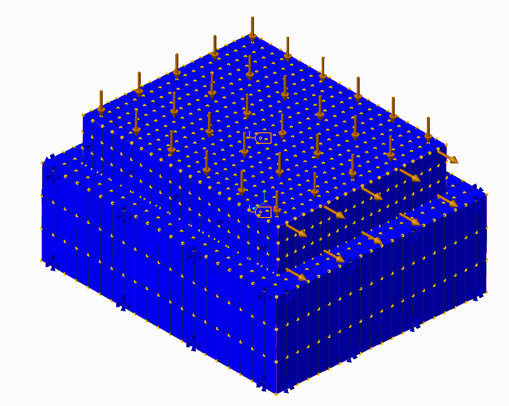
I used brick elements (tets give poor pressure plots and bricks provide a more 'stable' solution)

The problem is very 'sensitive' to the initial time step.

It will not solve using the default 0-1 ramp function with much oscillation of the residual norm, contact area reducing to zero followed by bisection after bisection then failing. The load factor is reduced to

Load Factor:  0.000195313

*** A fatal error has occurred. ***

There are 3 directions to explore

1. Load step refinement

2. Mesh refinement

3. This is a load rather than displacement controlled problem

LOADSTEP REFINEMENT:

With 10% timesteps, bisection still occurs but I get a solution and the results don't look right. Unrealistic displacement of the green block and a tangential force measure magnitude of 0.00757N where the applied load is 0.1N. The load factor is reduced by the software:

** Warning:

  Excessive motion detected at contact regions.

  Cutting load step size.

Load Factor: 0.025 (presumably of my 10% step)

The interface force is 7.48e-2 whereas the normal force applied is 2000N (presumed: the interface force measure is normal to the surface)

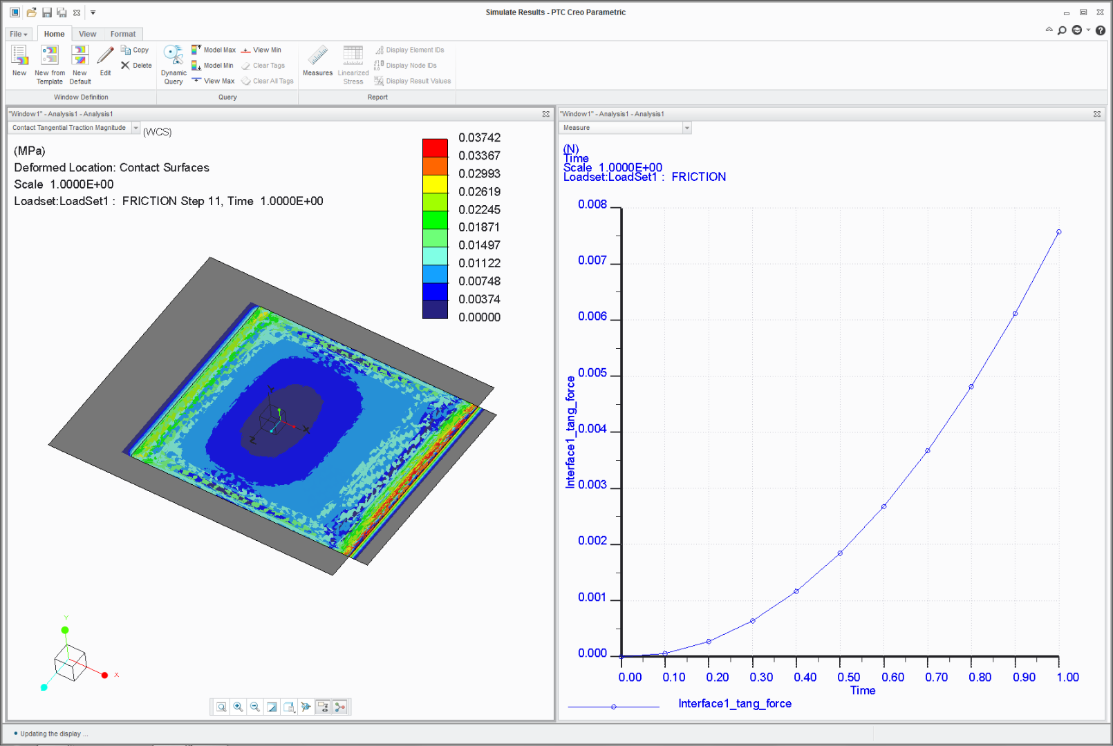
All the movement occurs in the first time step.

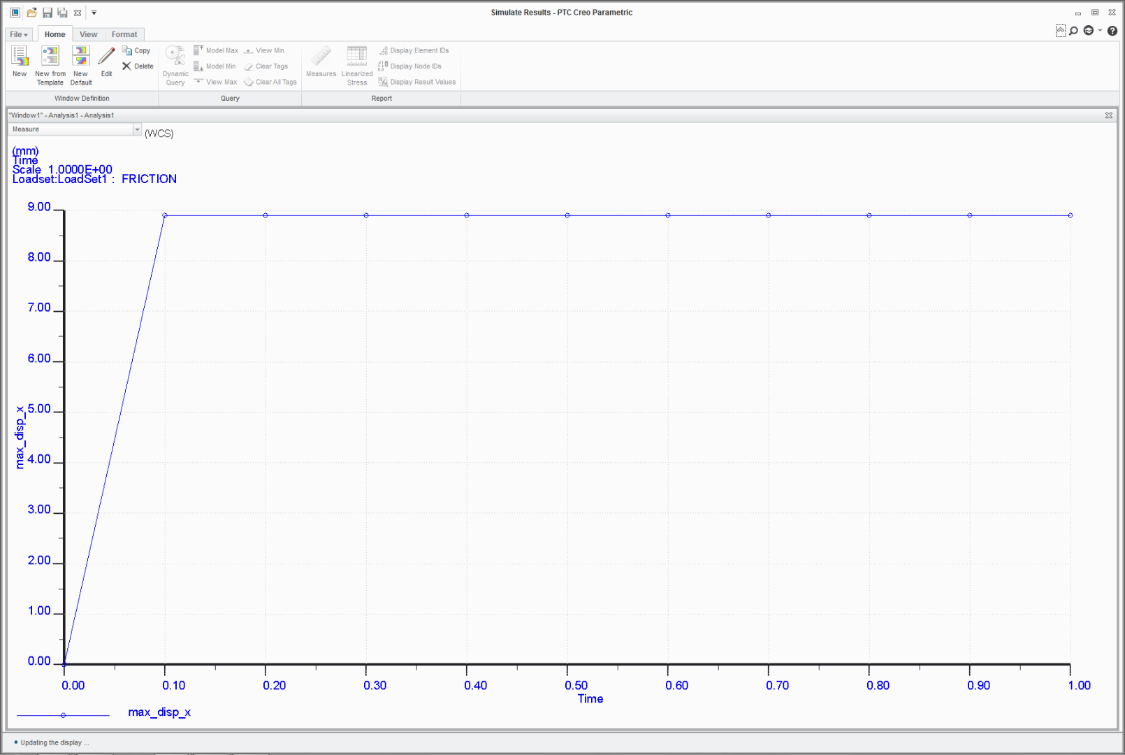
All this suggests poor mesh/loadstep selection.

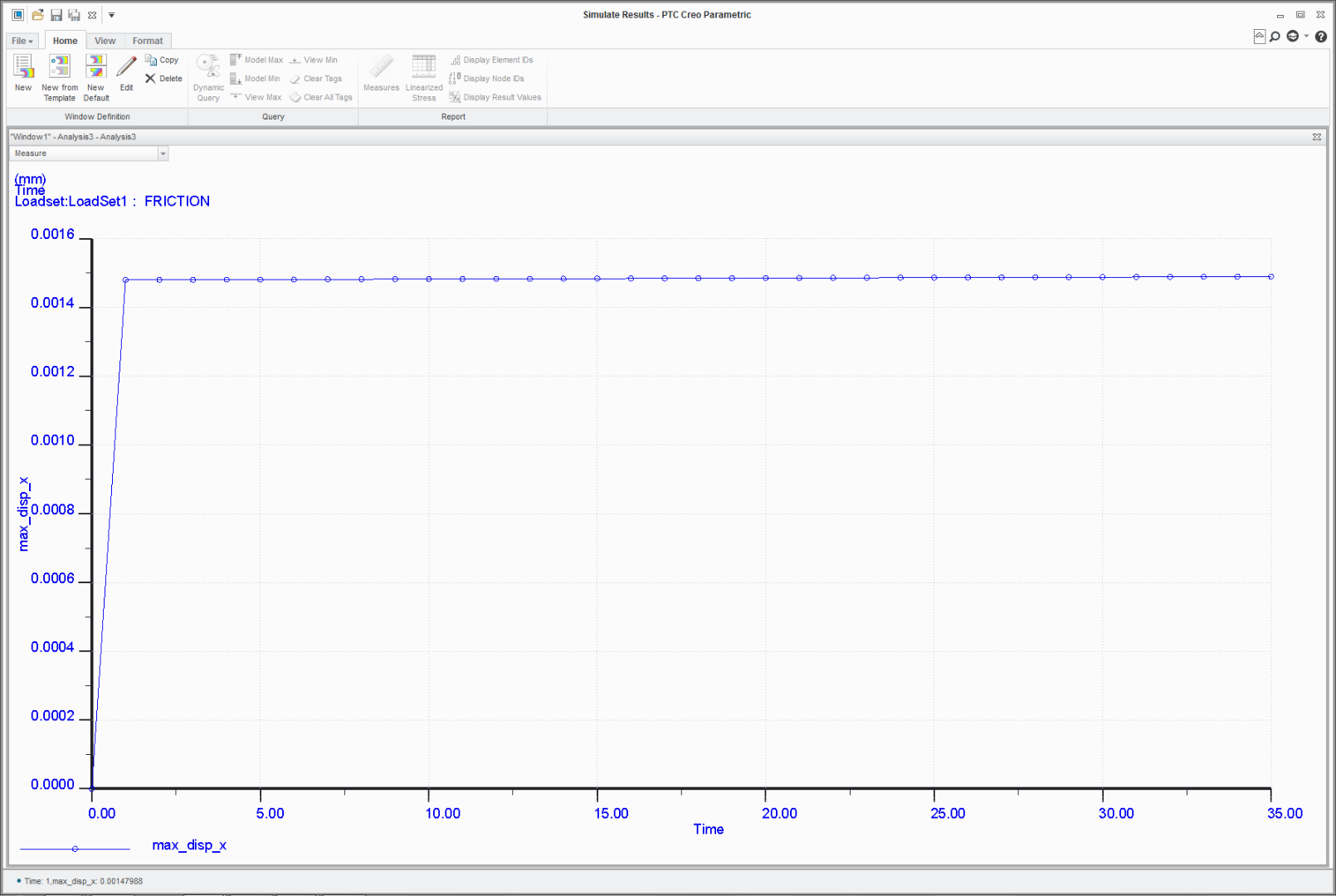
With 1% loadsteps there is some similar behaviour, just many more graph points (not all shown) and a lot more time (14658.75 secs vs 2246.68 secs)

There is a much smaller movement, with nearly all of it happening in the first loadstep with a very small increase in displacement each step after the first time step.

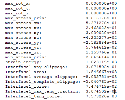
but now the tangential force measure doesn't stack up. The block is being pulled with 0.1N. The integral of tangential friction force across the contacting face cannot exceed the applied load.

      Interface1_any_slippage:           2.456282e-01

      Interface1_area:                         2.000001e+03

      Interface1_average_slippage:  -8.653680e-02

      Interface1_complete_slippage: -2.126610e-01

      Interface1_force:                       3.672802e+00

      Interface1_max_tang_traction:  4.273336e-01

      Interface1_tang_force:              4.515394e-01

the applied load pulling the block was 0.1N, the tang force is 0.45N

The resultant pressure load applied was 2000N, interface force is 3.67N

I should (and forgot) to create a ground constraint measure. Grrr.

So this is a mesh refinement thing? Should we have a finer mesh at the loaded edge? Should rounds be applied?

MESH REFINEMENT

Try tets? smaller bricks? Mesh is everything in Non-linear.

DISPLACEMENT CONTROL

A lot of problems have to be turned 'upside down'. Rather than applying the load an enforced displacement constraint is used such that a run-away condition is cannot be encountered; the model is always fully constrained. The reaction at the constraint is the load that would have otherwise been applied. This is how the examples posted on the learning connector (and others) work.

The problem with this is that the potential movements are so small. The green steel block is 50mmx40mmx10mm and if it's entire length 50mm length was involved in the stretching, it would have a stiffness of 10x40x200,000/50=1.6e6 N/mm. When the full load of 0.1N is applied then the extension would be 6.35e-8mm. The actual extension will be less than this as is seems reasonable that slip would only occur local to the loaded face initially with the rest of the contact interface effectively isolated and not moving. Surely therefore the enforced displacement constraint must have steps in the order of 10e-9mm or lower. I then have to question the mesh resolution again even though I know there are polynomials underneath.

So the fuzzy question is,  There will have been much testing on simple models such as this. Can we have some guideline re mesh, loadsteps and where it is not appropriate to apply finite friction, benchmark models?

Could my meanderings above be unpicked for a better understanding? and apologies in advance for any glaring mistakes, it has been a long (interesting) week.

En passant, what is the practical difference between asking for full results at user defined steps on the output tab and having a load that is factored by a function?

Thanks for getting this far

bfn

Best answer by rjakel

Hi all,

just last Tuesday I did a presentation about the new finite friction contact model in Creo 3.0 at the SAXSIM (SAXon SImulation Meeting, www.saxsim.de), Technical University of Chemnitz, Germany. It is attached for your information. You should obtain a lot of information regarding contact modeling in Simulate. After reading it, you’ll not be very surprised that all attempts to use Creo 3 finite friction contact are not very successful.

However, also Creo 2 users who just use the friction free and infinite friction contact models should obtain helpful information about code functionalities.

Fortunately, the new Creo Simulate responsible from PTC, Jose Coronado, participated to that meeting, too, since he did the opening presentation about the Creo Simulate 4.0 news. So, PTC has got the info.

Best, Roland


P.S.: I posted a lot of simulation-specific presentations under my new blog "Rolos Simulate Sources":

https://www.ptcusercommunity.com/blogs/RSS

I’ll update that from time to time with new material. Hope it's useful for you all.


7 replies

1-Visitor
June 15, 2015

It seems you are doing research on Creo/Simulate behaviour.... I doubt anyone has looked into this more closely than you have.

A few remarks:

* You have fully constrained the sides of the bottom plate. This may be why you do not get a nice even pressure distribution, because the sides of the bottom plate are now infinitely stiff

* Your top plate appears to be hanging over the edge, which would mean large displacements... not sure that is right?

* All movement in first step: that kind of makes sense because you will have micro-movements due to elastic deformations. Once that is settled, I can imagine there is no more relative movement b/c the tangential force cannot overcome friction. (I could even imagine that Creo first calculates elastic deformations and then contact in the next phase of the calculation, but that is pure speculation from my side).

346gnu13-AquamarineAuthor
13-Aquamarine
June 16, 2015

Hi Patrick,

Thanks for the notes.

I would not expect an even pressure distribution, both contacting surfaces are unconstrained and elastic. Ignoring friction for a moment, the contact pressure distribution will cause the green block to 'dome' with a lower pressure in the centre and the edges will dig in (I visualise it as a Gibb's effect). Cylindrical rolling elements in bearings have this problem and rather than rectangular cross section they can be given a curved profile (logarithmic) such that the pressure distribution remains linear-ish and peaks at the edges reduced/removed.

The top plate is hanging because is has moved 9mm in the first time step. This is not right. Movement has to begin at the loaded surface and 'propagate along' the structure (try dragging a carpet). In both models everything was in step 1.

The most bothersome thing at the moment is that the interface force and tan force measures are simply wrong (or a badly set up model coupled with poor interpretation).

ttfn

1-Visitor
June 26, 2015

Hi Charles,

I encountered the same problem. You did not mention you're datecode, but I tested it in M040 and it exists in that version. One of our customers came with the question. I opened a support case at PTC for this issue referring to this post because of you're precise explanation (thanks!).

Agnes


346gnu13-AquamarineAuthor
13-Aquamarine
June 26, 2015

Agnes,

I tried it in M010 and M030. (and Ansys).

Let me know what the outcome is.

Charles

1-Visitor
June 26, 2015

I'm curious... why do you want to do this in Creo if you can do it in Ansys?

1-Visitor
June 29, 2015

Hi Charles

Excellent job.

I've encountered similar problems with  "forklifting a pallet". friction, no friction, different meshes, timesteps, smooth load application, the works. But no convergence. To put it more bluntly, no succesful timestep at all, so no idea where it wants to move.

I also received this nasty remark of excessive motion, also a message that "full sliding has occurred at one of the contact surfaces" (which should be absolutely impossible given my constraints) I rebuilt the model in Creo 2 and the analysis runs without problems.

Something is not right in Creo 3.0

Contact_creo3.jpg

I would like to urge PTC to pay attention please. I can not use Creo 3.0 for normal business, which is a shame 10 months after the release was first presented.

1-Visitor
June 30, 2015

Steven

I've now seen 3 different models containing contact failing in Creo 3.0, which ran after rebuilding in Creo 2.0

It's simply not economically clever to move to Creo 3.0 I've not seen an advantage of the new contact algorithm yet, quite the contrary.

I will not start customer projects in Creo 3.0 until I'm sure it can be done effectively.

1-Visitor
June 30, 2015

Steven

I've tried finite and zero friction. no difference, no convergence in either case, for all 3 models.

My 3 Examples contained flat planes under normal load, concentric cilinders, 1 supporting another and a model with a tube in a hole. friction or no friction, contact did not converge in creo 3.0, but did converge (no friction) in creo 2. I've not tried infinite friction.

Erik

1-Visitor
July 6, 2015

Hi All,

PTC has acknowledged that the tangential forces are NOT correct; SPR 4571852 with HIGH PRIORITY, for those who can view it.

I'm not sure about the rest of the results;

-You're 'average slippage' measure is (very) negative, so telling you there is NO SLIPPAGE (seems correct)

-The displacement you show is only in the outline of the block, not in the centre, so is this slippage or just deformation of the block as a result of the forces?

Furthermore, it is clear that to get (probably) correct displacement results with finate friction (in the current release) you MUST have about 11 time-steps and a very fine mesh. With standard analyses settings the study will report large displacement but in my experience it does not report that convergence is not obtained. However, the fact that it jumps in a SPA from poly 3 to 9 does indicate it.

1-Visitor
July 22, 2015

Dear Charles,

New work around provided by PTC R&D;

In the current release of Creo 3 (m040) in order to get correct results for Interface_force with finite friction you need to set the following settings;

- Contact should be surface-surface (not component-component)

- Use study type Quick Check (SPA is currently not correct)

- Ensure you have at least 10-11 time steps

I've tested it and my Interface_force is now correct! Try it, I would say...

I'm still in discussion with R&D about the tang_traction and the max_tang_force results...


1-Visitor
August 31, 2015

I have a reaction from PTC about the tang_traction and the max_tang_force;


“The measure  Interface1_max_tang_tractioncan be used to get the required tangential force as: tang_force = Interface1_max_tang_traction*  Interface1_area 0.02749214*900 = 24.7429. This is one
of the workaround to get there – work in QC (Quick check) Analysis as discussed.  This is approximate solution
because we are calculating this from MAX traction and not from average traction.  The other workaround is to use
enforced displacement loading instead of force as I demonstrated in my earlier mail.”


"The measure Interface1_tang_force was incorrectly reported by engine in Creo 3.0 and R&D is
working on this.  There are other SPRs on this same line about this tangential force measure and R&D have plans to fix them by December 2015 end.  R&D will provided a fix in the next Creo 3.0 M080 Datecode versions for all SPRs those falls on this line.  Hope that is not too late. Sorry for delay
and I appreciate patience."


I would say, applause for PTC for listening and committing yourself to a fix-date!

rjakel1-VisitorAnswer
1-Visitor
March 25, 2016

Hi all,

just last Tuesday I did a presentation about the new finite friction contact model in Creo 3.0 at the SAXSIM (SAXon SImulation Meeting, www.saxsim.de), Technical University of Chemnitz, Germany. It is attached for your information. You should obtain a lot of information regarding contact modeling in Simulate. After reading it, you’ll not be very surprised that all attempts to use Creo 3 finite friction contact are not very successful.

However, also Creo 2 users who just use the friction free and infinite friction contact models should obtain helpful information about code functionalities.

Fortunately, the new Creo Simulate responsible from PTC, Jose Coronado, participated to that meeting, too, since he did the opening presentation about the Creo Simulate 4.0 news. So, PTC has got the info.

Best, Roland


P.S.: I posted a lot of simulation-specific presentations under my new blog "Rolos Simulate Sources":

https://www.ptcusercommunity.com/blogs/RSS

I’ll update that from time to time with new material. Hope it's useful for you all.


1-Visitor
June 2, 2017

PTC's answer to this discussion presented at SAXIM 2017, 28 march

FYI 'next buildcode' at that time could be m130 which was released in April of this year.

346gnu13-AquamarineAuthor
13-Aquamarine
November 19, 2021

Still doesn't work in Creo 7

24-Ruby III
December 17, 2021

@hhiller @jchelle @aoualim Could you please help with this?