I'm a little confused on what your analysis setup is suppose to be for the assembly level or what the goals of the analysis are (stress, displacement, etc.). Could you put something together describing the real-world problem you're trying to simulate and what you want to capture.
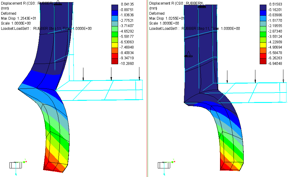
For your part level analysis, part of the reason why your analysis took so long to run is that you're having numerical stability issues. If you look in the .PAS file, you'll see several pseudo time steps are taking 100-150 iterative steps to convergence on an acceptable residual nor level, and on a couple different occasions your stiffness matrix becomes singular. If you look at the first pass results, you'll see that the outer most tip of the flange displaces more that its radius; this means that you applied load is now going to be a (mostly) shear load on the surface. This in combination with the very large displacements you're having is part of the reason why the analysis is taking so long to run.
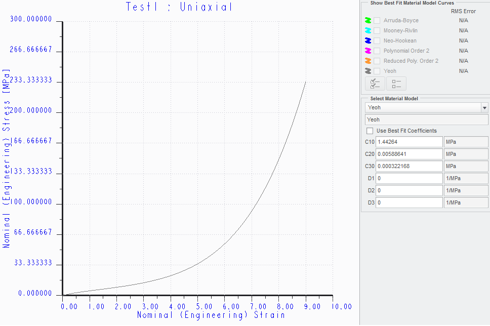
Now, if you want to try to approximate a contact surface between the inner curved surface of the rubber part, then you could create a cylindrical coordinate system and constrain the surface in the radial direction (but remember, the surface will not be able to move in the + or - R direction). Looking at the stress-strain curve for your hyperelastic material models makes me think that this assumption isn't too bad. From a strain of 0 to 5 your stress increases by about 30 MPa, giving a linearized Young's Modulus of about 6 MPa; after that, the next linearized Young's Modulus would be about 50 MPa. Your base material has a Young's Modulus of 7 GPa, so we have about 2-3 orders of magnitude greater stiffness on the base. You can see how this helps reduce the displacements, but you will have the flange deformed to a vertical position. At this position do you really expect to have a 10 N load vertically down (which, for the deformed shape, would be something like a friction load).