1-Visitor
July 27, 2013
Question

how do you constrain to a floor when simulating?

  • July 27, 2013
  • 2 replies
  • 12974 views

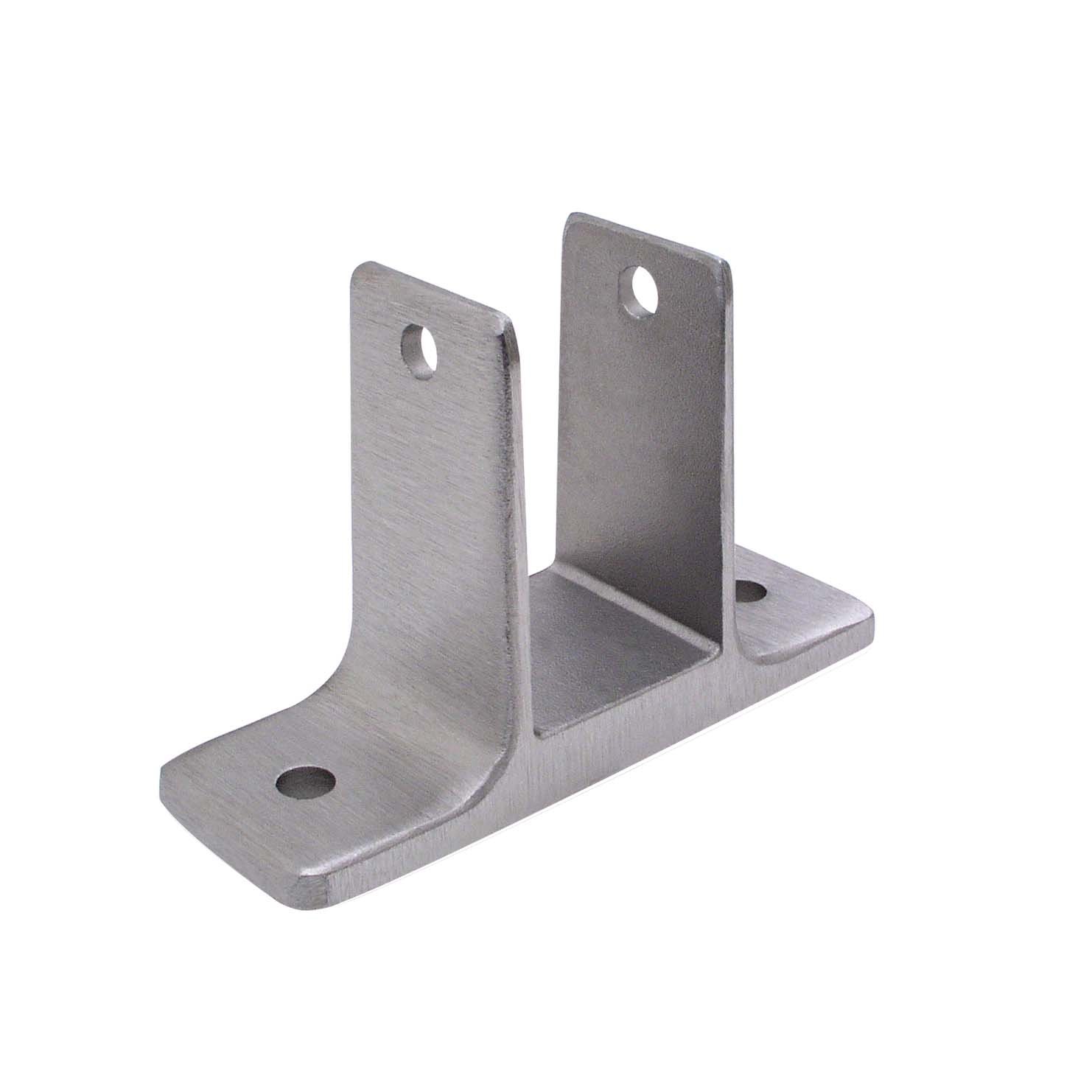
I have a simple bracket which is supposed to be bolted to a horizontal floor. See image for an example.

I would like to do some finite element analysis on the bracket.

A force is applied on the bracket vertically up.

How do I set-up the constraints properly? If I simply constraint the bottom surface of the bracket, the results are wrong, because in reality the bracket will only be constrained to the floor where the bolts are going into the floor!

If I only constrain a surface region on the top surface of the bracket where the bolt is touching the bracket, then its also no good, because in reality the bracket is unable to bend downwards (into the floor).


I would like to do it in part mode in CREO 2 simulate (and not assembly mode, where I would simply model a floor and bolt, because I only want to see deformations of the bracket).

Please help..


1833.jpg


This thread is inactive and closed by the PTC Community Management Team. If you would like to provide a reply and re-open this thread, please notify the moderator and reference the thread. You may also use "Start a topic" button to ask a new question. Please be sure to include what version of the PTC product you are using so another community member knowledgeable about your version may be able to assist.

2 replies

1-Visitor
July 30, 2013

Hi bj p,

Have you tried modeling the floor and creating a contact analysis?

bp_011-VisitorAuthor
1-Visitor
July 30, 2013

Yes, but how do I make the bolts and floor infinitely stiff?

1-Visitor
July 30, 2013

Create a rigid link for the bolts and the floor. A rigid link prevents the part from deforming = infinitely stiff.

13-Aquamarine
July 30, 2013

Since you want the bracket to be able to separate from the floor but not penetrate it, I think you have no choice but to create an assembly and run a contact analysis.

I would model the floor as a large rectangular block, and create a material for it with an appropriate elastic modulus (you could use just a large number, say 10x - 50x the modulus of the bracket, although http://www.engineeringtoolbox.com/concrete-properties-d_1223.html suggests that concrete is actually less stiff than aluminium). You could constrain the other five faces of the 'floor' to keep it well supported, although a more realistic constraint might be to lock the underside and create a mirror constraint on each of the four sides.

For a simple approach you could define a surface region on the bracket where the head of the bolt sits, and use a rigid link to connect this to the floor; really, I think you should probably look into fasteners although I have no experience of these.

When viewing results, remember that you can set Location -> By Component and isolate just the part you want to view, although I don't think there's a way to view displacements relative to an arbitrary datum.

bp_011-VisitorAuthor
1-Visitor
July 30, 2013

Ok guys, thanks sofar..

Ive created a rigid link on the top-surface of the "floor", and constrained all other sides.

I got the following warning when the top-surface was also constrained while having the rigid link:

"The dependent side geometrical references may be in conflict with another rigid/weighted link or constraint".


I have made the floor-bolts part of the floor .prt so I dont need to create constraints for those..

So far so good.

Ive placed a simple horizontal bolt trough the bracket clevis-arms, and put a vertical force on the surface of the bolt which pulls the bracket up.

When I run a simulation I get a warning for these surfaces:

"A portion of the highlighted load/constraint is applied to an internal surface"

So how do I make CREO understand that this bolt is infinately stiff and will apply a simple force on my bracket without error?

This horizontal bolt has a head and a screw, so the clevis arms should be able to bend outwards, otherwise I would simply apply the force vertically on the clevis-arm holes.

1-Visitor
July 30, 2013

For the horizontal bolt, make another rigid link and select all surfaces of the bolt. Don't forget to set up your contact surfaces.

I did a quick test and had success. For the floor and integrated mounting bolts, I made all surfaces part of the original rigid link except for the bottom of the floor where the constraint was applied.

You can see from the image that Creo treats the bolts and floor as infinitely rigid because they have no stress....infinitely rigid = no nodal displacement = no stress. To get the rigid parts to look the way they do below, I set my legend lower limit really small and changed the lower limit color to light gray. For the image of just the bracket, I did as Jonathan suggested and isolated the bracket in the display location tab. Not a real thought out run, just something real quick to show the method.

bracket0.JPGbracket1.JPGbracket2.JPG