1-Visitor
August 2, 2012
Solved

How to create a step cross section view in ring

  • August 2, 2012
  • 1 reply
  • 4486 views

Hi,

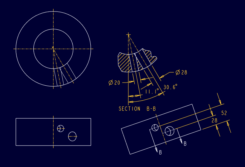
I would like to create a cross section veiw in my deatil(drawing) to show to holes which direct to ring axes but different level, the Pro E (WF4) help sail the only can create Parallel section by planar or offset optional.

of cause,I can create two cross sections to show the two holes, but I want to show it in one, thank you in ahead.

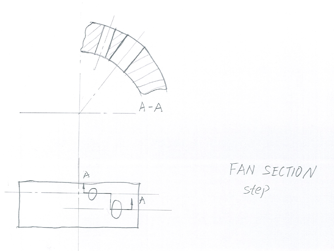
follwing hand drawign shows what I want.

Best regards, Hongjie

step cross section in ring.png


This thread is inactive and closed by the PTC Community Management Team. If you would like to provide a reply and re-open this thread, please notify the moderator and reference the thread. You may also use "Start a topic" button to ask a new question. Please be sure to include what version of the PTC product you are using so another community member knowledgeable about your version may be able to assist.
Best answer by TomD.inPDX

Not that I know of. Someone may have a better solution. One problem is that both holes overlap from top down near the inside edge.

Proper drafting technique would be similar to this:

step_section_drawing_ii.PNG

1 reply

17-Peridot
August 2, 2012

For rotational object, the step section is not very powerful but functional.

You were almost there. I made the step section sketch on a datum plane perpendicular to DTM4.

If you want the arrows to show correctly, you will need an auxilery view to show the step.

step_section_model.PNG

step_section_drawing.PNG

Hongjie1-VisitorAuthor
1-Visitor
August 3, 2012

Hi Dirriwachter,

thank you for help!

Does it mean that ProE WF4 can not cut model rotationally to a axis and only perpendical to datum plane? if it is right, it should be better to use two cross sections to show in detailing (drawing) which do not have any deform for above example.

Best regards, Hongjie

17-Peridot
August 3, 2012

Not that I know of. Someone may have a better solution. One problem is that both holes overlap from top down near the inside edge.

Proper drafting technique would be similar to this:

step_section_drawing_ii.PNG