1-Visitor
November 20, 2016
Question

Model to Help 5th Graders Understand PTC Coordinate System

  • November 20, 2016
  • 8 replies
  • 12678 views

I've made the following model with which I hope to explain the PTC coordinate system to 5th Graders.  I've succeeded only in confusing myself.  Maybe you can help.


CoordinateModel.png

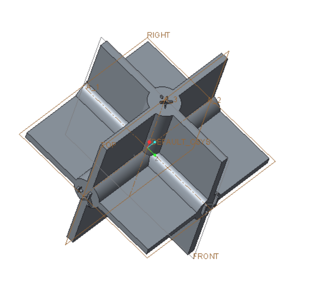
The file is attached.  Created with Creo Parametric 3.0 M070 Academic.  I think this a right hand system as pictured,  I've extruded X+, X-. Y+, Y-, Z+ and Z-.  I want to extrude (20mm) FRONT+, FRONT-, TOP+, TOP-, RIGHT+ and RIGHT_ on the planes  I presume that FRONT+ is on the Y+ side of the FRONT plane.  Am I on the right track?


It seems to me that the default system in Creo Academic is a left handed system!!!


This thread is inactive and closed by the PTC Community Management Team. If you would like to provide a reply and re-open this thread, please notify the moderator and reference the thread. You may also use "Start a topic" button to ask a new question. Please be sure to include what version of the PTC product you are using so another community member knowledgeable about your version may be able to assist.

8 replies

1-Visitor
November 20, 2016

The usual interpretation is that X is right, Z is up and Y is into the screen.

Right+ => X+,

Front+ => Y-

Top + => Z+

The names of the planes are arbitrary, but each coordinate system has labeled axes and Creo is entirely right-hand.

1-Visitor
November 21, 2016

Specifically for the Front orientation , X+ is right and Z+ is up on the screen. At least I consider it that way because the screen is typically vertical.

24-Ruby III
November 21, 2016

Hi,

in Creo you can:

  • create empty part (no features)
  • create 3 default datum planes a give them requested names
  • create coordinate system and orient its axes using existing datum planes as references
  • save the model

Later you can use this part as template model.

MH

1-Visitor
November 22, 2016

You may be underestimating the intelligence level of your 5th graders.  You may also want try the tri-metric default view, instead of the more common isometric view.

Bob Schwerdlin

torme1-VisitorAuthor
1-Visitor
November 22, 2016

They certainly will not have any more difficulty than I am having.

Top-Bottom

Right-Left

Front-Back

1-Visitor
November 25, 2016

‌The way we were taught the general 3D coordinate system was to extend the 2D plane to 3D so the XY plane was the front view and the Z axis extended toward you. The 3D region of X+, Y+, and Z+ was considered to be in the same position as the 2D region of X+ and Y+ and viewed the same way with X+ to the right and Y+ to the left. This was then extended to explane rotations of the coordinate system that are commonly used in other areas. We commonly use the -XY plane as a front view.

torme1-VisitorAuthor
1-Visitor
November 25, 2016

I think I'm on the right track;

I want make twelve gray planes labeled

Front Y-

Right X+

Top Z+

Back Y+

Left X-

Bottom Z-

six blank plane

Two red dowels labeled

+

-

Two green dowels labeled

+

-

Two blue dowels labeled

+

-

With a single color printer all of these, I should be able to make these parts (when I have a 3D printer).  The planes will have 50mm x 50mm notches so they fit into the dowels.  Overall dimensions of the model are 10cm X 10cm X 10cm.

I'm stuck on the dowel problem.  I can't get rid of the four unwanted protrusions so I get a pointed squarish end..

dowellC161125.png

1-Visitor
November 25, 2016

Two options come to mind if I understand the end you want to have, I'm assuming a pyramid. Create planes through the two surfaces of each triangular extrude and use solidify to remove the unwanted geometry. You could also create a blend that blends a square to a point. This is done by using two sections: 1) the square and 2) a point.

Here are images showing each option:

1) planes using solidify to remove

solidify.jpg

2) blend of square to point

Blend.jpg

17-Peridot
November 25, 2016

I use this but claim no right or wrong in it's interpretation   By default, in the commercial version, that makes FRONT the X(pointing right)-Y(pointing up) plane with Z coming at you.

torme1-VisitorAuthor
1-Visitor
November 26, 2016

Your model suggests some new designs.  It lacks the XYZ indicators.  This can be easily corrected.  I suggest the following:

NewPart161126.jpg

NewpartB161126.png

If you want a color coded system you need three parts.  Then all surfaces and dowel ends must be labelled correctly.

1-Visitor
November 28, 2016

Antonius Dirriwachter had the best reply of all.  Simple and easy to understand.

Bob Schwerdlin

1-Visitor
November 28, 2016

Antonius Dirriwachter had the best response of all.  Simple and easy to understand.

Bob Schwerdlin

17-Peridot
November 28, 2016

Thanks Bob.  You might look at something to clarify the difficulty understanding this process.

There are two standards that manage how you "unfold" a drawing.  The version I use is 3rd angle projection.

There is also a 1st angle projection.  This is a typical projection used by ISO.

Most drawings will have a small symbol on it to show how to interpret the views.

The concept is how the views fold out from the main view.

The question that you will inevitably hear is "...why is the left side of the car called right?"

My answer is "perspective"... and of course, that starts a much longer discussion.

1-Visitor
November 29, 2016

I've always looked at this simply this way:

If you are using the default planes and csys, and you orient your model to "Top", you are looking directly at the TOP plane. If you want to look at the Left or Right, you are looking at the SIDE plane. If you want to look at the front or back, you are looking at the FRONT plane.

It may help to use the View Manager to orient your views and highlight the TOP/SIDE/FRONT planes.  I'm not sure if the setup at my company is out of the box, but it does list clearly which direction X/Y/Z is going (+ or -):

cone_default.JPGtop_cone.JPG

torme1-VisitorAuthor
1-Visitor
November 30, 2016

Many thanks!  Your jpg's show clearly a right hand system.  My focus now is to design a model students can actually make with a 3D printer (which we will get soon).  The candidates are given below.  The design of the center requires some thought.  I can make dowels with cone points, but I haven't been able to make points which will completely fill center.  I want to keep the suggested RGB = XYZ mnemonic.  Dowels in Model 1 can be color coded with a single color 3D printer and PLA spools of different colors..  As you go from 3D to sketch mode 2D the process is "almost" slow enough to see what is happening.


Model 1

cube.JPGcubeleft.JPG

dowelA.JPGdowelB.JPG

Alternatively,

Model 2

color.JPG

I still have to "square the cone."

1-Visitor
November 30, 2016

I'm glad the jpgs helped!

If the cones are the issue, have you considered using stepped cylinders for the axes for your block assembly design (design 1)? You could add a hole in the middle for the crossing axes to pass thru and could also step the bores in the block so it can only be assembled one way.....you'd need various  sized cylinders, of course.

stepped_axis.JPG

Your 5th graders will have a nice puzzle in the end!

Debbie