1-Visitor
September 4, 2015
Question

Proper way to dimenion a rounded corner? (ASTM Y14?)

  • September 4, 2015
  • 5 replies
  • 20263 views

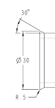
I'm having an argument with a vendor who made my part incorrectly.  I do not know the ASTM code very well so I'm seeking advice.  What is the proper way to dimension the part below?  I've obviously chosen to dimension to the radius point and not the theoretical sharp.  Is there ASTM code that covers this?  I also sent the model to the vendor but he's saying I've dimensioned it wrong in the drawing and that's what he went by.


This thread is inactive and closed by the PTC Community Management Team. If you would like to provide a reply and re-open this thread, please notify the moderator and reference the thread. You may also use "Start a topic" button to ask a new question. Please be sure to include what version of the PTC product you are using so another community member knowledgeable about your version may be able to assist.

5 replies

23-Emerald IV
September 4, 2015

I don't know about ASTM, but it seems pretty straight forward.  The dimension doesn't say "to apex" or "to theoretical point", so if you put a set of calipers on it and it doesn't measure 30, it's not to print and made wrong.

1-Visitor
September 4, 2015

Thanx Tom. I dimensioned it like that EXACTLY for that purpose.  Its impossible to measure to a theoretical sharp.  The issue is my vendor is saying its improperly dimensioned. If someone knows the code and can quote it for me, that would allow me to settle the case.

23-Emerald IV
September 4, 2015

One question, does your print explicitly state that you dimension everything in accordance with ASTM Y14?  If not, then he can't hold you to it.  If so, then have him prove in the standard where what you did is wrong.

1-Visitor
September 4, 2015

I do not see a detailed explanation of "theoretical corners" or "theoretical sharps" in my copy of Y14.  Although there are some sections that state when a dimension is applied to intersecting surfaces, "crossing extension lines" should be used (sections 1.7.2, 1.7.2.1, 1.7.2.2).  I would challenge your vendor to provide a copy of his standards, maybe we can all learn something.

Nevertheless, your design intent is what needs to be conveyed.  I would interpret your drawing to indicate that it is diameter 30 on the outer radius surface itself, not the "theoretical" sharp.  In my practice, if I ever provide a "theoretical" dimension, I would add that statement to the dimension or feature.  Also, show a scaled-up detail view whenever important features like this can be misinterpreted.  Good luck.

1-Visitor
September 4, 2015

Thanx Jeff.  That is actually a good idea. I will see if I can get him to provide the standard.  I too will always add a note if dimensions are not to actual geometry.

1-Visitor
September 4, 2015

I've attached a scan of the page from Y14, glad to help a fellow grunt. 

12-Amethyst
September 4, 2015

Anthony,

ASME Y14.5 Dimensioning and Tolerancing does not dictate how one should dimension a part but the language of dimensioning.

It is up to the user to determine the need and constraints for dimensioning of features and to be clear and concise without interpretation.

If you use solid models to build, follow ASME Y14.41 Digital Product Definition and Data Practices (as you mentioned you sent the model), but this also need to be defined.

Not knowing what the issue is, what you have provided seems proper to begin with but there is missing information and "grammatical" errors.

Can you provide more information as to the why the part was made incorrectly?

Ron

1-Visitor
September 4, 2015

When asked why the part was made improperly this was the response:

____________________________________________________________ 

If they wanted a .020 radius at that point they should have defined that
center location of the .020 radius, so you have the correct 30 deg location.
That would have defined the 1.181dia correct.

The angle and the .020 radius is defined correct with the given information
on the print.

Yes I can rework and adjust my CAD to get the .020 radius in the location
they want.

____________________________________________________________


If you ask me, he doesn't really have a clue, but he wants me to pay the tooling charge to change the mold.  I have asked him if he interpreted the drawing the way he states in his response.  If he did, then the part would have been BIGGER not smaller.

23-Emerald IV
September 4, 2015

Huh?  The .02 radius is continuous from the vertical line to the angle line...

1-Visitor
September 4, 2015

So all this said, I feel I can make the statement that the drawing is clearly and sufficiently dimensioned per ASME Y14.  Would anyone disagree?

Also, I got this response from the vendor...


The 30mm diameter was drawn from the 34.2 dimension then the 30 deg angle was struck at that dia then the .5 radi was drawn.


In the upper right view you are showing the 30 degree angle is defined by the 30mm diameter.


That is standard engineering practice for definition of an angle on a diameter.


They clearly used the 30mm dim as the sharp point.  But he later suggested that I should have done this instead...

Either way, I did NOT add any extension lines or centerlines so he should have properly interpreted my drawing.

23-Emerald IV
September 4, 2015

That is standard engineering practice for definition of an angle on a diameter.

Maybe for them.  It's only universal if actually written in a universal standard somewhere.