14-Alexandrite
August 24, 2023
Solved

Question regarding shell

  • August 24, 2023
  • 4 replies
  • 8617 views

Hello,

I am trying to recreate this model from solidworks modelmania 2013. (https://blogs.solidworks.com/tech/wp-content/uploads/sites/4/Model-Mania-2013-Phase-1-Drawing.jpg)


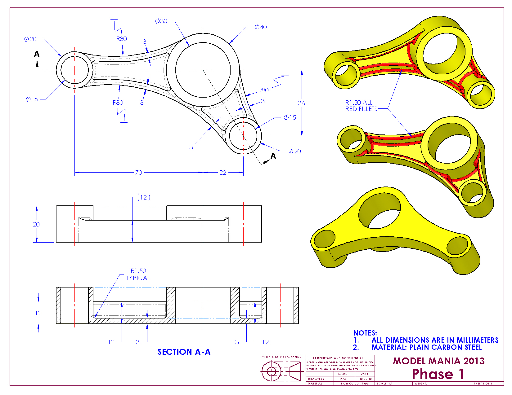
I thought about using the shell feature for the offset walls of value '3' circled below.

IbrahimTayyab_0-1692905053408.png

I believe I would be able to do this by using the shell, exclude surface feature however I was unable to do that; and it does make sense since the surface is not extended down into the other surface.

IbrahimTayyab_2-1692905219299.png

In the end I decided to use non-default thickness and it worked fine.

IbrahimTayyab_3-1692905262319.png


I wanted to ask how you would approach this? As always I really appreciate all your help.


Using Creo 9.0

Best answer by Pettersson

If you're on Creo 7 or later, this sounds like a job for multibody modeling. Make the cylinders and the connecting parts as separate bodies. Here's a quick demo:


  1. Make a master sketch containing the three circles and the tangent lines.
  2. Use Sketch Regions to extrude the entire sketch (including the cylinders) to the base thickness.
  3. Extrude only the three circles, using Sketch Regions, as a separate body.
  4. Shell the main body.
  5. Subtract the cylinder body from the main body, while keeping both (so don't remove the cylinder body).
  6. Shell the cylinder body.
  7. Merge the two bodies together.

If you don't like using sketch regions (to be honest, I don't), you could do the same thing by just constraining the cylinder extrude to the first extrude sketch. That's probably better, to be honest. Fewer references that risk breaking.


Pettersson_0-1692950171432.png


4 replies

tbraxton
22-Sapphire II
22-Sapphire II
August 24, 2023

Another method would be:

Create the "floor" 3 mm thick shape and then use thin option extrusion for the 3mm vertical walls on the perimeter of the floor by projecting the loop of the floor perimeter. This will give you the pockets that the shell yields.

14-Alexandrite
August 24, 2023

I tried doing that but I can't for some reason any idea what the problem might be?

The sketch.

IbrahimTayyab_0-1692907148882.png

Extruding as a surface or solid works. 

IbrahimTayyab_1-1692907205428.pngIbrahimTayyab_2-1692907221853.png

But thicken sketch doesn't work I suspect it due to the corners being too close.

IbrahimTayyab_3-1692907267064.png


tbraxton
22-Sapphire II
22-Sapphire II
August 24, 2023

Create the shape in the top view. Then raise the walls around the perimeter. Refer to the video as a guide.

14-Alexandrite
August 24, 2023

The second phase of this challenge is as following. The main difference being there's is a partial "shell" feature/cavity on both sides that do not extend throughout the faces. 

Would there be a possibility to shell still or is the approach as I suspect to remove the material by using extrude or perhaps using tbraxtons method.

kdirth
21-Topaz I
21-Topaz I
August 24, 2023

I would stick to my previous answer, but each cylinder and each "floor" would need to be created individually.

There is always more to learn.
kdirth
21-Topaz I
21-Topaz I
August 24, 2023

I would create it this way:

  • Extrude 3 cylinders
  • Extrude three walls (Using Thin intrudes on inside of cylinders)
  • Extrude floor using project
  • Add rounds
There is always more to learn.
15-Moonstone
August 25, 2023

If you're on Creo 7 or later, this sounds like a job for multibody modeling. Make the cylinders and the connecting parts as separate bodies. Here's a quick demo:


  1. Make a master sketch containing the three circles and the tangent lines.
  2. Use Sketch Regions to extrude the entire sketch (including the cylinders) to the base thickness.
  3. Extrude only the three circles, using Sketch Regions, as a separate body.
  4. Shell the main body.
  5. Subtract the cylinder body from the main body, while keeping both (so don't remove the cylinder body).
  6. Shell the cylinder body.
  7. Merge the two bodies together.

If you don't like using sketch regions (to be honest, I don't), you could do the same thing by just constraining the cylinder extrude to the first extrude sketch. That's probably better, to be honest. Fewer references that risk breaking.


Pettersson_0-1692950171432.png


14-Alexandrite
August 25, 2023

I just learned that you can extrude sketch regions and what multibody modelling is, this is so good. Thank you very much for the guidance, I never realised the significance of bodies before this.

kdirth
21-Topaz I
21-Topaz I
August 25, 2023

Looking at your video, the thin extrude would work the way you are creating the cylinders as solid, then extruding holes later.  I was extruding cylinder walls that are 2.5 mm thick.  When thickening a line by 3 mm that is tangent to the cylinder it thickens 0.5 mm inside the cylinder.


In your video, the thin extrude does not work because the thickining lines clash at the bottom of the large cylinder.  Try going around the outer perimeter with your lines and it should work fine.

There is always more to learn.