1-Visitor
February 14, 2015
Question

Sheet Metal Roller Bead

  • February 14, 2015
  • 5 replies
  • 15780 views

I want to add a bead to a sheet metal part. It will follow the contour of another feature already placed. I could do a form tool and punch it in the part but I was hoping there is another way. I would like to sketch my trajectory on the part and have a the shape sweep that. But so far I dont see a way.

Here is a sample picture of something like I want.

rollerbead1.jpg

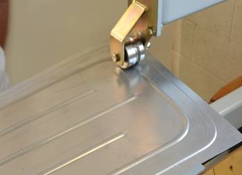
This would be the tool that would do it,

http://www.mate.com/en/products-and-parts/fabrication-solutions/rollerball/http://


This thread is inactive and closed by the PTC Community Management Team. If you would like to provide a reply and re-open this thread, please notify the moderator and reference the thread. You may also use "Start a topic" button to ask a new question. Please be sure to include what version of the PTC product you are using so another community member knowledgeable about your version may be able to assist.

5 replies

17-Peridot
February 15, 2015

I am not a fan of the punch tools since they are kept outside the model. I opt for a surface form tool.

That way I generate the surface just like you suggest and then using the surface to form the metal isn't too troublesome at that point.

You can therefore use all your familiar commands to create the surface including reusing common references.

1-Visitor
February 15, 2015

http://www.mate.com/en/products-and-parts/fabrication-solutions/rollerball(The original link is mis-posted)

Interesting tool - I like the video

The Mate Rollerballâ„¢ tool creates stiffening ribs and decorative beads in sheet metal parts without a secondary operation. It is available in popular tool styles including: Ultraform for Thick Turret, Thin Turret, 112/114, and Trumpf style.

1-Visitor
February 17, 2015

Sorry about the link. I didnt notice the extra http remaining after I cut and pasted.

Looking at other cad packages It looks like they have a feature specifically for beads. I dont see this in Creo. I dont like form features either but since it would take more work to make the feature come out correct without a form tool , and I will be needing a very similar feature in a few other other parts Im afraid the form tool is what I will have to use. PTC reallly needs to add funcitonality for a bead feature. Thanks.

1-Visitor
February 17, 2015

I just made a quick look for beading in other packages; only found it so far in NX NX Sheetmetal 18 BEAD - YouTube and SolidEdge Solid Edge Short: Sheet Metal in Solid Edge ST6 - YouTube courtesy of a compliant that Inventor did not. Overdue Improvements to Inventor Sheet Metal: - Autodesk Community which is a really interesting list of things for sheet metal to do. I did notice that the Solidedge version is unrealistic in its handling of sheet metal - the beads would certainly collapse if they were bent like the model shows.

15-Moonstone
February 17, 2015

i think the sketched form tool is your answer. they have added that from creo 2.0.

you have to just sketch the shape..it has to be closed sketch.

17-Peridot
February 17, 2015

I never figured out how to correctly use the sketched forms.

Ken, the feature is there, it just isn't prettied up like other offerings.

A path, swept arc, and quilt form. Done:

quiltform.PNG

1-Visitor
February 17, 2015

Ok this looks promising. I have not tried this method before and so far I must be missing something as I cannot get it to work.

Here is my panel with the swept surface along the sketched trajectory (the cutout on the left). The straight bead along the bottom I did with a form tool.

When I get in to Quilt Form and select the surface previously created I cannot get it the create the sheet metal feature I tried various combations of the options. Thanks for the help with this.

panel1.JPG

panel2.JPG

panel3.JPG

1-Visitor
February 17, 2015

I too would like to know this and I only know how to do it by using a form.

I love sketched forms, but that just makes a sink unless I'm doing it wrong.... right?!?!? As a one click type solution a sketched form is pretty sweet, saves a ton of time combining all the offset and merge action, but is there a way to make a thin, or sweep it as a ball somehow? Please share your method here, my technique probably goes back to pro 17.

I have oil canned all kinds of sheet parts for stiffness but a separate form tool is what I usually use. Since the rounds and interfaces can get wacky as well, I usually put those shapes on the form and get them to regenerate successfully on the punch then let it propogate away. I guess I have had better luck going crazy on the form to get the shape correct because once it's stable, it seems to stay put and behave.

I do not run PDM here, but when I have done this same dance at client sites, seems that the dependency gets found and the form part just checks in along with the rest of the parts like its normal. Maybe that's an admin setting somewhere I don't know, but personally I've never had an issue where the form gets lost or unattached or whatnot.

In any case here are three forms, the sketched one basically makes a sink and not a ringed ball deformation which seems to be the OP. I added the optional rounds to that and even some taper just to push it around. The other two shapes on the corner are both on a single form, one is a straight circle sweep, the other is arc based so the rounds work out, but you can see both trajectories because they merged over. Pictures below since they are so much easier to track.

tl;dr - would like to know how to do a ring shaped ball deformation please

snap4257.jpg

sketched form section

snap4258.jpg

sketched form options as shown, sketch is closed loop rectangle with round fillets (8 entities)

snap4259.jpg

form tool (old school?)

snap4260.jpg

section view of forms

snap4261.jpg

three forms, two pushes, one form, one closed loop, none exactly do the roller ball thing per the video above

snap4262.jpg

roller ball like deformation from a form, but it's not quite Jedi level stuff....

1-Visitor
February 17, 2015

Gary, you gave me an idea and it worked. I did two additional sketches with a turn down on both ends of my original sketch. This causes the sweep to go off the surface and not have an uncapped end when the quilted form is created. Not sure if this is any less trouble than doing an outside form but maybe. At least the feature is contained in my part without an external reference. Thanks!

panel4.JPG

1-Visitor
February 17, 2015

Are you surfacing this with trim's and merge and stuff??

snap4263.jpg

snap4264.jpg

Patriot_1776
22-Sapphire II
November 28, 2016

Funny, the "Quilt form" seems to not like rounds that become tangent to the plane on the "punch" side.  And adding the rounds IN the feature doesn't work either.  Not good.  Am I missing something?  You'd think the "placement" and "non placement" edges would work......

17-Peridot
November 28, 2016

It likes to optionally add its own rounds based on the sheetmetal bend radius setting.

Patriot_1776
22-Sapphire II
November 29, 2016

In my case in doing a "bead" like this with a hard start/stop and no "lead-in" or "lead-out" (meaning the end should be spherical), it flat refused to put a radius anywhere.  And if I modified the quilt to add a radius tangent to the "punch" side plane and equal to material thickness, it did some really weird stuff.  But, I'm a total novice to sheetmetal stuff, so......