1-Visitor
August 21, 2014
Solved

Surfacing Help: Style Surface Boundary Conditions

  • August 21, 2014
  • 2 replies
  • 8899 views

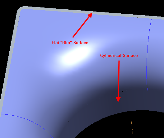
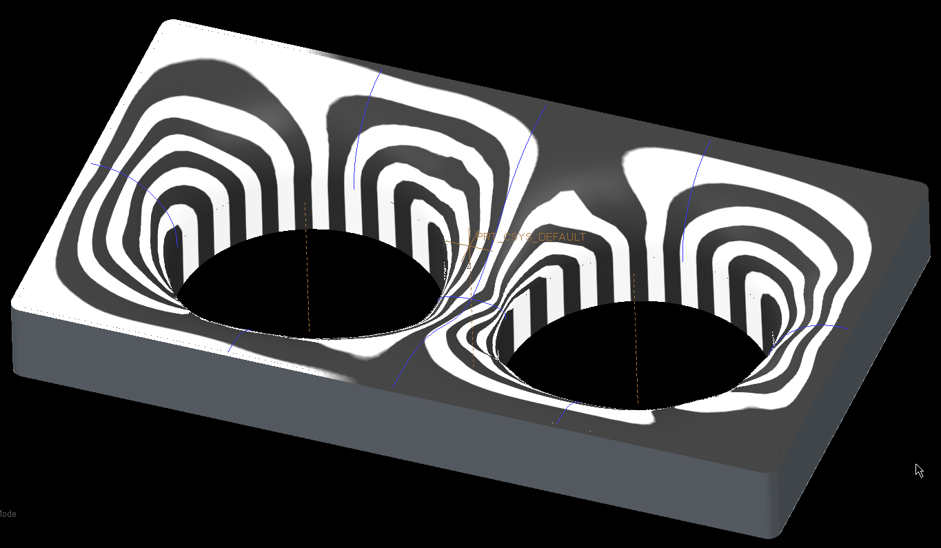
I've been working more on this shroud (http://communities.ptc.com/thread/56128) and now I'm trying to figure out how to control the boundary conditions of a style surface.

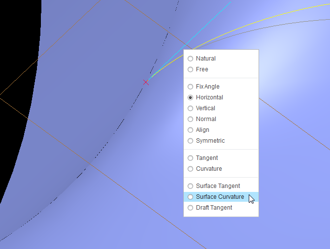
The boundary conditions at my edges where I have control curves are good (i.e. they are curvature continuous and normal to the plane, but in between control curves the surface does not keep that condition.

SNAG-0384.png

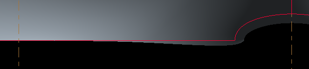
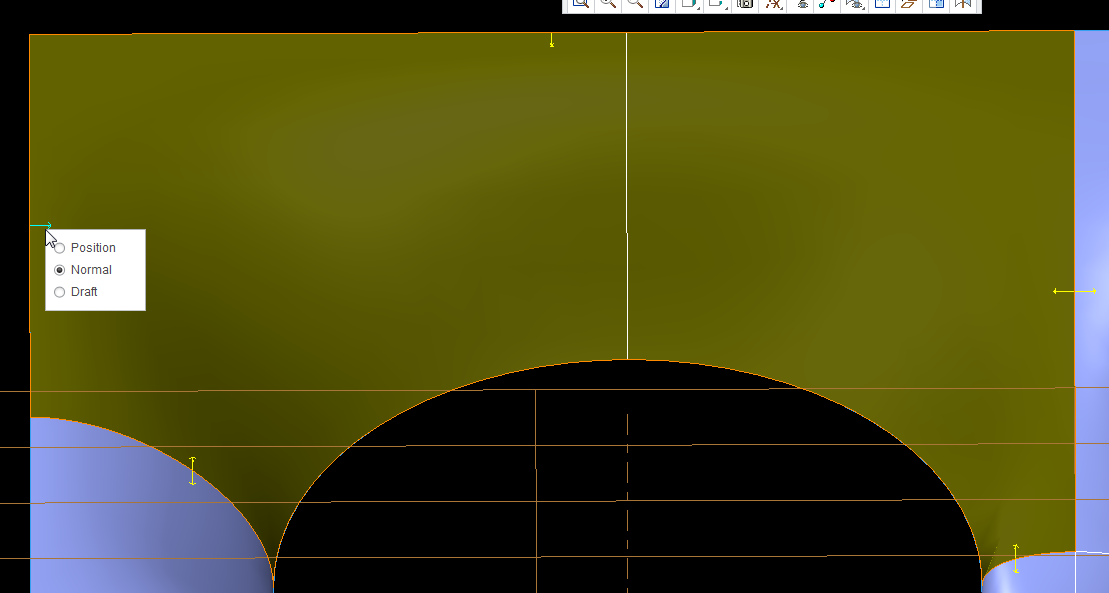
This becomes obvious when I thicken the surface with a normal offset. If the surface were normal, the part of the edge would be coincident with the horizontal red line (surface edge).

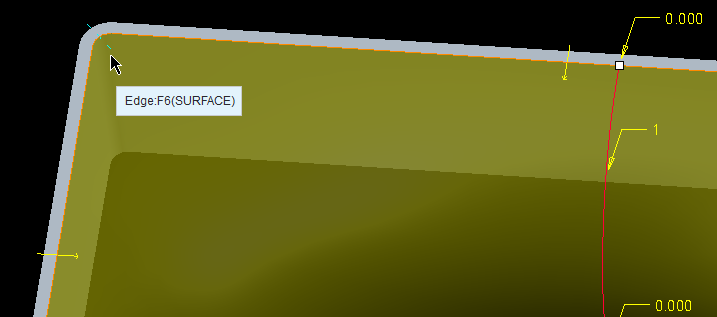
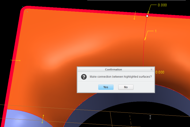
All of my edged except for those on the inner circle have edge control arrows. Why don't the arcs?

8-21-2014+12-24-40+PM.png

Best answer by Dan_Harlan

Ok, making progress.

First thing I found (and my first mistake) was thinking that the wireframe curves would be sufficient for defining the curvature was wrong.

Second, I found that the surfaces (even if the part won't actually have those physical surfaces) adjacent to the smooth (G2) surfaces must be defined. In my case, these were the two cylindrical surfaces that represent the final smooth airflow direction and the 'rim' type surfaces perpendicular to the airflow.

SNAG-1007.png

With those surfaces, I could then go and define the end points of my styles curves to be Continous.

SNAG-1003.png

Then I could go and make connections between the style surfaces and my reference continuos surfaces by selecting the broken line indicators.

SNAG-1004.png

If more than one surface was possible, then you would get a prompt like this (asking if the red surface was the correct surface to connect to).

SNAG-1005.png

Once those connections were made, then I could set those connections to be surface continous (they defaulted to tangent).

Still have some investigation to do and cleanup, but this looks like a solid solution.

SNAG-1006.png

2 replies

1-Visitor
August 22, 2014

Hi,

Use cylindrical surface instead of the arc curve to be able to set the boundary condition for the compound surface you are making.

If your curves don't have curvature continuous connections with the adjanced surfaces then the surface you are making won't be curvature continuous either.

1-Visitor
August 22, 2014

Not quite sure what you are meaning. I've attached the file so you can take a look.

The center circle is just that, a circle. The guide curves are style curves; planar, 3rd order, two points only with end point conditions of either horizontal or vertical.

Dan_Harlan1-VisitorAuthorAnswer
1-Visitor
August 22, 2014

Ok, making progress.

First thing I found (and my first mistake) was thinking that the wireframe curves would be sufficient for defining the curvature was wrong.

Second, I found that the surfaces (even if the part won't actually have those physical surfaces) adjacent to the smooth (G2) surfaces must be defined. In my case, these were the two cylindrical surfaces that represent the final smooth airflow direction and the 'rim' type surfaces perpendicular to the airflow.

SNAG-1007.png

With those surfaces, I could then go and define the end points of my styles curves to be Continous.

SNAG-1003.png

Then I could go and make connections between the style surfaces and my reference continuos surfaces by selecting the broken line indicators.

SNAG-1004.png

If more than one surface was possible, then you would get a prompt like this (asking if the red surface was the correct surface to connect to).

SNAG-1005.png

Once those connections were made, then I could set those connections to be surface continous (they defaulted to tangent).

Still have some investigation to do and cleanup, but this looks like a solid solution.

SNAG-1006.png

17-Peridot
August 22, 2014

Be careful with mirrors. I am seeing some interpretation going on when you mirror with some assumptions. not every feature truly mirrors! I noticed this when I used curvature analysis but it was clear with the knot analysis...

shroud.PNG

the left is a mirror of the right where a C2 curvature was chanded to a simple arc.

This is actually a fairly disturbing development. the left side is the mirrored feature.

shroud_II.PNG

Both sides are treated equally. there is no reason for this to have developed differently. Each mirrored feature was investigated for commonality.

23-Emerald IV
August 25, 2014

Mirror the quilt instead of the features. Much more robust.