Wow... I'm just getting to all these posts from back in August! I'm really sorry I fell off the map but the world caved in on me over the past 6 weeks or so...
I realize this is probably so old no one even cares anymore... but there is a way to do what you're asking for.
First, rule #1: never take anything PTC technical support says as gospel...ever. At least half the time they'll tell you something is impossible even when it is possible. Often PTC technical support doesn't understand their own product as well as the designers and engineers that use it every single day. They're not very flexible. If the "answer" to your question is not in their system, "it's impossible".
Sometimes you get lucky and you'll get a support tech that actually attempts to help you. Maybe they spend 5 minutes trying to resolve your issue. They try all the same buttons and switches you've already tried, fail, throw their hands up, and proclaim "it's impossible".
Well, no, it's not impossible. It's a little bit of a pain in the neck but it's certainly not impossible. In my opinion, PTC's technical support personnel should know this software inside and out. They should be able to give you an answer and then let you decide if the method required to incorporate that answer is too much work. But the tech support personnel do not know the software... they're basically about as good as your everyday average "power user". They know a bit more than the basics- and the rest they get from their knowledgebase. If the answer isn't there- :shrug: oh well, it's impossible.
But enough pontificating... what's the solution?
Whenever you have a dimension with a plus/minus or symmetric dimension, you can access the values of those dimensions using parameters in a relation. Here's an excerpt from the help files:
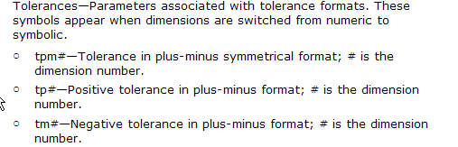
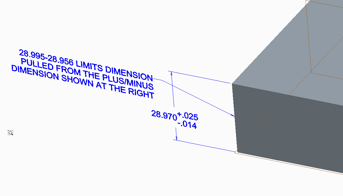
So then... set your dimensions in the model to plus/minus even though you want to display limits. This will allow you to access the tp (positive tolerance) and tm (negative tolerance) values for the dimension as well as the dimension itself. Create a relation to generate the limit values. If you were interested in generating the limits for dimensions &d14, the relations might look like this:
x1 = d14 + tp14
x2 = d14 - tm14
d14 is the dimension number (use switch symbols to see the dimension numbers)
tp14 is the upper tolerance value for the d14 dimension
tm14 is the lower tolerance value for the d14 dimension
Change the "14" to whatever number dimension you're intersted in.
In your note, simply use &x1 and &x2 to access the limits dimensions.
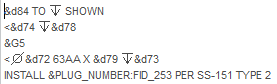
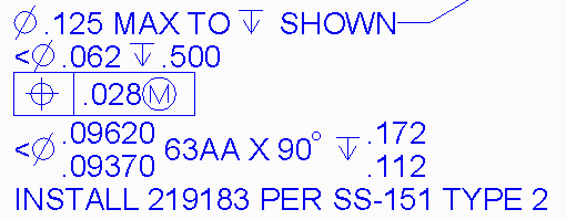
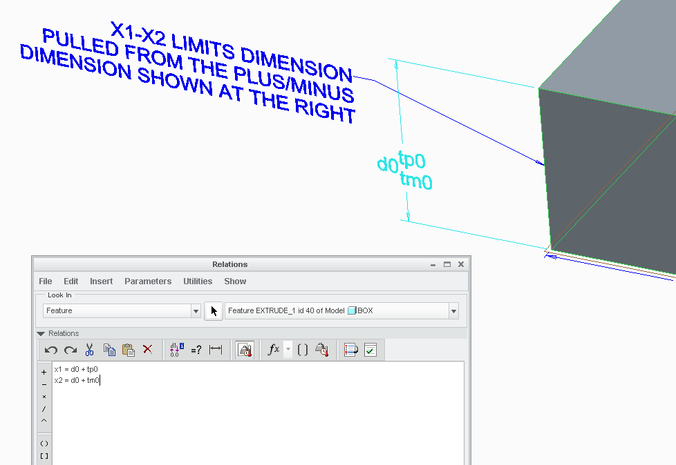
The only trick here is where to place these relations. You can put them in the part- but this is cumbersome. I'd suggest putting them in feature relations. In the image below, notice the relations window is set to "FEATURE" (upper left hand corner of the relations window). The relations I used are displayed. Also, you can see the dimension values toggled using the switch symbols command. You can see that the dimension number is "0" (zero). The relations do not clutter the part because they're stored in the feature. Those relations give you the ability to display your limits dimensions however you wish in your note. (Click the image to see a larger version)
Pretty doggone simple... and not nearly as "impossible" as you were led to believe.
The just serves to illustrate my earlier point... surely someone working for PTC as a full time tech support person should be able to offer up such a simple, convenient solution. Why don't they? Anyone... anyone... Bueller?
Hope that helps!
-Brian