15-Moonstone
July 27, 2016
Solved

Trouble with matching tilted customer sections

  • July 27, 2016
  • 3 replies
  • 6951 views

I need to build a preform type model based off a customer model.  I want the new model to be totally independent of the customer model.

The customer model has a number of tilted cross sections that I need to match.

From a previous Creo forum post I am trying a method to place my tilted datums that I will place sketches to match the cross sections.

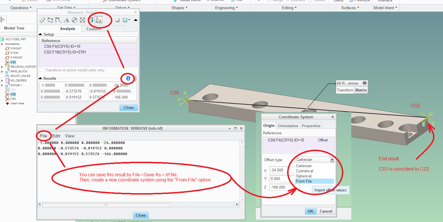
The method that I am using is to 1st place a tilted coordinate system and then place the datum plane on the coordinate system.

Before I do this I generated a temporary datum plane off 3 points on the tilted cross section.  I place a central point on a sketch driven off the temporary datum plane.  This gives me a XYZ location of the coordinate system which I build.

Next comes the problem; I need to tilt the coordinate system to the same inclination of the temporary datum plane.

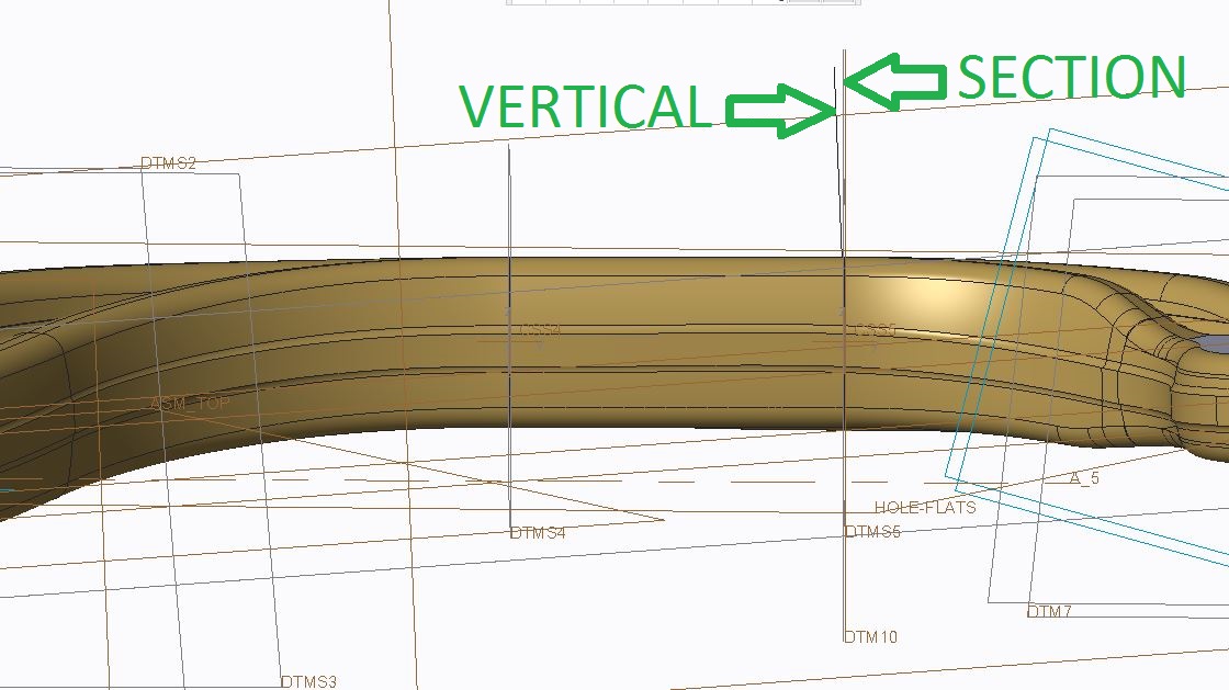
Laying this in my top view I can measure a angle that would be rotated around my Z angle in the coordinate system.  (I make a top view sketch and project a line down to the top datum and measure this angle.  SEE BELOW)

Z angle.JPG

This gives me my Z axis rotation value.

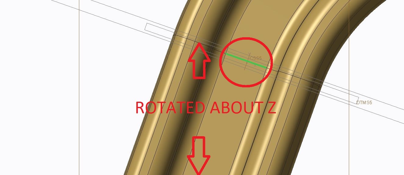
Next I take the green line shown circled in the picture above and extrude this in the Z direction.

If you look at this normal to the temporary plane you can see that there is a small amount of rotation from the vertically extruded line.

X rotate.JPG

I capture this value and it becomes my X rotation.

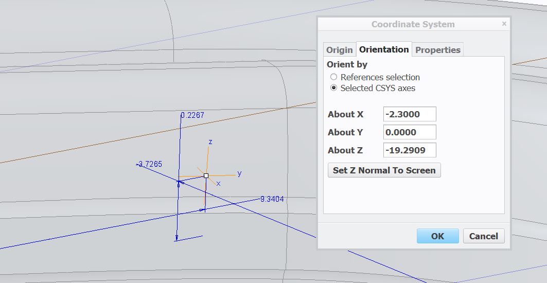
My coordinate system has the following rotation values.

Coordinate system rotations.JPG

When I place my datum plane to this I go back in to analyse the resulting rotation value between the temporary and placed datum.  I want the value to be 0 just like the distance, but here is what I get.

datum compare.JPG

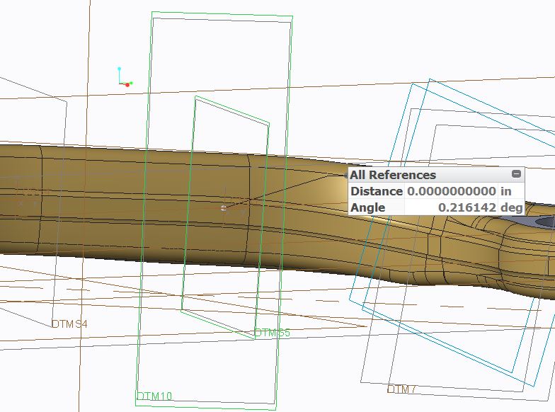
I really don't know how to evaluate the above .216 value.  I can see that I have a small rotation error in my model, but I don't know what direction this error is in.

I did not rotate anything in the Y axis, but I really couldn't see how to even determine this value.  I was hoping that this rotation wasn't even necessary.

Would anyone have an idea of how I could lock on to the XYZ rotations to match the customer sections?


This thread is inactive and closed by the PTC Community Management Team. If you would like to provide a reply and re-open this thread, please notify the moderator and reference the thread. You may also use "Start a topic" button to ask a new question. Please be sure to include what version of the PTC product you are using so another community member knowledgeable about your version may be able to assist.
Best answer by psobejko

In Creo 2.0, you can use the measure tool to get the 3x4 transformation matrix from one coordinate system to another.  You can then capture that information to a .trf file, and then use that file to specify how a coordinate system is positioned/oriented with regards to a reference coordinate system:

coordinate_system_transforms.png

3 replies

pimm15-MoonstoneAuthor
15-Moonstone
July 27, 2016

A little update.

Above I noted that I didn't apply any rotation in the Y axis because I didn't know what to even rotate about.

The sections are all ribs.  I took the central thin section of the rib and placed a X direction line parallel to the thin section.

I measured the difference between the X direction line and my top plane and I used this value as my Y rotation.

This tightened my difference to perhaps .1 degrees but I'm still not exact.  I'm not sure that I can get exact when the tilt is applied to all directions.

1-Visitor
July 29, 2016

When you place the coordinate system, pick the datum plane first to set the orientation, then pick the datum point to set the location. There should be a final pick to finalize the orientation.

23-Emerald III
July 27, 2016

Are you translating and rotating the coordinate system? I have found that either I get confused or pro/e gets confused when I translate and rotate. I usually translate with one coordinate system and then rotate with another one tied to my translated coordinate sys.

pimm15-MoonstoneAuthor
15-Moonstone
July 27, 2016

Stephen,

You may be speaking about positioning the main CSYS or possibly all the downstream CSYS.  In either respect I would agree with you about the confusion.

I do use a main sub coordinate system to rotate my solids, but in this case I am talking about numerous coordinate systems to develop the datum positioning.

Below you can see the end result of what I am needing.  The datums were developed from the customer model but now they are all independent (albeit with a small amount of error).

I might be able to have exact datum placement if I were to copy geom a number to the faces from my customer geometry and do planes to 3 vertices, but the below method is much cleaner.  Just wish there were a way to get exact results.

Datums positioned.JPG

17-Peridot
July 27, 2016

Can you not take the transformation matrix of a coordinate system using references and duplicate it in a new coordinate system?

2-Explorer
July 28, 2016

There's one more technique I've used when doing piping assemblies.  You create the csys using external references, then redefine in the subassembly and pick the default csys (assuming you have one) in the model.  The external references are removed and the csys dimensions are filled in correctly.  I think in your case you'd have to create a couple of dummy assemblies that you could delete when done.  I've attached a Powerpoint showing the steps.  It sounds harder than it is, once you've been through it.  Any way, it's one more weapon in the arsenal.

23-Emerald III
July 28, 2016

YES, I've done it this way before. I couldn't remember the detail though. You are right, it sounds complicated but it's really simple and quick.