1-Visitor
January 31, 2013
Question

Creating bellows with VSS and trajpar?

  • January 31, 2013
  • 4 replies
  • 7065 views

Hey everyone, long time listener first time caller here.

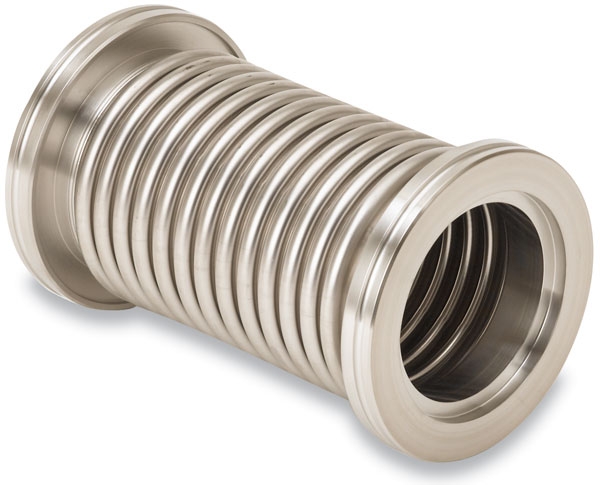
I'm trying to make a model of a hydraulically formed vacuum bellows as shown in the picture below (taken from Kurt Lesker's website).

Photo-HD-FC_MH_QF_E06.jpg

I can model both flanged ends fine, but I am struggling with the center ruffled section. I could make a revolved section, but that would require sketching out each individual ruffle. I could model a single ruffle and pattern it the necessary number of time to create the part, but what happens if I wanted the part to follow a curve? In short, I'm looking to create the bellows with some elegance, sophistication, and intelligence such that I could potentially make it a flexible part in an assembly or possibly make a family table of bellows (easily). I originally thought a Variable Section Sweep would be the way to go, but I can't get it to work. I will show my current approach below. If someone could tell me why my approach won't work, and give me some advice on how to move forward it would be very much appreciated!

I start with a datum graph of a single rib as shown below (called graph1):

graph.png

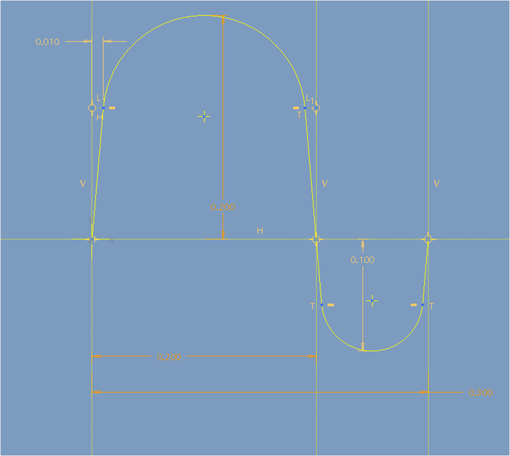
The x-axis represents the nominal diameter of the ruffled section. If I know the x-position of any ruffle section, than I can get the value that I need to add to the nominal diameter from the corresponding y-value on the graph.

To calculate the correct x-value, anywhere on the ruffled section, I use the image below:

variable_def.png

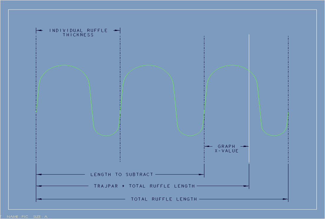
I need the graph x-value. I can get that value by the following formula:

x-value = (trajpar * total_ruffle_length) - length_to_subtract

where:

length_to_subtract = floor( (trajpar*total_ruffle_length) / individual_ruffle_thickness) )

so the general equation (which should work for any number of ruffles and any length of tube) is:

x-value = (trajpar * total_ruffle_length) - floor( (trajpar*total_ruffle_length) / individual_ruffle_thickness)

--

As I write this, my equation is the same thing as using the mod() function:

x-value = mod(trajpar*total_ruffle_length, individual_ruffle_thickness)

--

So I create a Variable Section Sweep with a straight line as the trajectory. I make the section in the sketch as a circle (lets call its diameter sd3). In relations I make the diameter of the circle to be:

sd3 = the_nominal_ruffle_diameter + evalgraph("graph1", x-value)

where the x-value is the value defined above. So the equation should return a y-value of the graph for every trajpar of the line and add it to a nominal diameter. The equation is itself extremely general and is independent of number of ruffles. Logically, this should work (who knows if my logic is in itself logical... but that is a different forum post altogether). Unfortunately... pro/e won't create the sweep. Can anyone help me out as to why? Or how I can create the feature?

Many thanks!


This thread is inactive and closed by the PTC Community Management Team. If you would like to provide a reply and re-open this thread, please notify the moderator and reference the thread. You may also use "Start a topic" button to ask a new question. Please be sure to include what version of the PTC product you are using so another community member knowledgeable about your version may be able to assist.

4 replies

17-Peridot
January 31, 2013

I only see two problems with your approach... having worked in vacuum products for years. Do not make your next-level assembly models this complex. First of all, you are going to be setting the precedence and second, sustaining a complex piece of geometry will be a headache years down the road. Even though the math is easy on the CPU, the graphics horsepower required will have a negative impact.

Having said that, and if you need a detailed model such as this in only a few specific instances, indeed, make the part as you need for that instance in whatever means that works. I would consider using Warp to quickly form the part to a shape you need on the fly.

In my experience, I would model this as a swept tube (a spline can be straight or curved). You might make the length variable, and you can add instances for various curves. If you really want to maximize utilization, make it a flexible part with the right interfaces to simply fit the tube at the assembly level. ...just not with the convolutions.

If you want it to be representative in the assembly, consider a central tube of the actual material thickness as the minor diameter. On top of this, as a transparent surface or similar thickness solid to represent the OD. Alternatively, put the solid centered in the total thickness and place two transparent surfaces on the ID and OD. You get my drift...

Welcome to the forum!

knorman1-VisitorAuthor
1-Visitor
January 31, 2013

I certainly appreciate everything in your response. To be honest this was more of an experiment to test to see if I could make the bellows with the approach in my original post and if so, to test the stability of such a process (the stability question was quickly answered).

While I will ultimately create the final model using simple tubes to represent the ID and OD of the model as you suggested, modeling the corrugated surface using the Variable Section Sweep has become a bit of a personal battle with Pro/E. I'm not going to roll over that easily, and am willing to commit a bit more of my personal time on this part to try to figure out what is going on. Pride before the fall...

I was able to kind of get my method to work.

bellows_part.jpg

The only way I could get the geometry to work was to change the end value on the trajectory to a smaller value as shown (circled in maroon) below:

bellows_changed_value.png

A small range of values work. To be honest I still don't know why this change in values does the trick, or really how those parameters affect the overall model. I will have to do some reading/research on the variable section sweep, but if anyone has a quick explanation it would help put me at ease.

All in all, I think it was a useful introduction into the more powerful features of pro/e (datum graphs, relations, and variable section sweeps), even though the final part may not be useable in any but the most detailed of models.

17-Peridot
February 1, 2013

The place I run into most solve issues is in the sketch itself. Even though you can "sneak up" on a particular dimension, you cannot do it in one fail swoop. It is like you sketch some shape and then try to size it. If you change a dim by more that 50%, the sketch either ignores your input or just makes the geometry incompatible. Eventually, you can get the sketch to conform to your will. I suspect the same is happening with your initial sketch in the change. You might be able to make small changes at a time and eventually end up with your end means. For such cases, you must apply limits to your constraining dimensions.

This will be fun to play with. I've done some very powerful things when it comes to bellows using sketches. One thing I always had trouble with was when they go straight (if they are intended to be bent) and when you go past straight (tilt the other way).

Patriot_1776
22-Sapphire II
February 1, 2013

It's good to see people using advanced features like graphs, especially when linked to a VSS. Bravo Kyle.

While that certainly can be done, I think I'd be more apt, in this case, to simply use a pattern of the bellows and use relations to control things. I'd also make it a family table part, and use a spinal bend to get the curved part after the fact.

17-Peridot
February 1, 2013

I forgot about Spinal Bend. That Spinal Bend dialog always gets me.

It certainly is more controllable than Warp but has to be done prior to the fixed/undistorted geometry.

1-Visitor
February 1, 2013

Dear Kyle,

Is it not possible with thin revolve feature?

knorman1-VisitorAuthor
1-Visitor
February 1, 2013

A thin revolve feature is definitely possible. When I was first thinking about the different methods available to model the part, I did indeed contemplate using the revolve tool. I decided against it because I thought I could create a more robust, stable, and flexible part by using the Variable Section Sweep tool driven from a graph and relations. Theoretically, my approach should work independently of the number of corrugated ribs, the length of the tube, the diameter of the tube, or the overall shape of the part. The idea was that all you had to do was sketch one rib in a graph, sketch a trajectory, and let pro/e do the rest! While it works great in theory (doesn't everything?), the actual model didn't turn out to be robust, stable, or flexible (bummer).

As it turns out, I think I will go back and try to model the part with a revolve feature, pattern, and spinal bend as suggested by Frank. I've never touched the spinal bend tool, so this will be a good opportunity to try it out.

17-Peridot
February 1, 2013

Let's see what you guys think of the attached.

The Spinal Bend trajectory is a spline with 3 controlling values. The convolution is drag-able with the handle between the two arcs. Convolution section is a bit, well... convoluted and can be simplified but the Spinal Bend is particular about the starting location. In general, the overall scheme would be a bit more controlled, defined and refined.

If the spine sketch could be made "flexible" for the next level assembly, you would have a good flexible connector. I'd be interested in how this can be accomplished down to a tutorial level. I have no clue as to how flexible parts are managed in real life. I've seen the spring examples.

bellow_spinal_bend.JPGbellow_convolution_handle.JPG