17-Peridot
January 11, 2016
Question

Mesh of revolution

  • January 11, 2016
  • 6 replies
  • 11370 views

There is no a command that permit to you to do a mesh of revolution using the "advanced tool" introduced with the Creo release: the mapped mesh option and the prismatic element option.

For example, I'm trying to do a 3d mesh on this quarter of screw.

Cattura.JPG

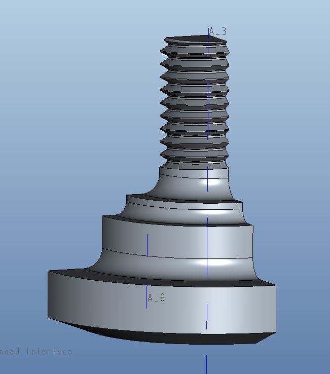
How can I do otherwise?

Thanks.

    6 replies

    13-Aquamarine
    January 11, 2016

    Hi,

    Similar was discussed in the following thread with some reasonable (?) conclusions

    Mapped Mesh on Fillet

    Your thread is a helix though. You would have to compromise and make the thread a revolve.

    Regards

    1-Visitor
    January 12, 2016

    This was possible in the old Mechanica Independent mode... But as Charles pointed out, you would then have to compromise and make the thread as a revolve,not a helix. And if you do a revolve, then I'd model it one element thick, as an "almost 2D"-model. And if you do that, no element can touch the revolve axis at a corner; all elements must have an edge along the revolve axis. There are no elements that describe the shape of a triangle or quad revolved around an axis that intersects only a corner of that tri/quad.

    gfraulini17-PeridotAuthor
    17-Peridot
    January 12, 2016

    Hi,
    I've already done the 2d axisymmetric analysis (with contact) and now I try to do the same within the 3D environment.

    2d.JPG

    Allow to the mesh engine the task of making the mesh is not the right way, for me, because it generates a tetra mesh; this means:
    - high number o elements
    - tetra elements are not the best choice for contact analysis
    - much time for results

    But this geometry is not simple...

    Ah...I'm using Creo 3.

    1-Visitor
    January 12, 2016

    That makes sense, but in 2D you can not, at least in Creo 2, combine plasticity, large deformations and contact. Large deformations is necessary in this case since it is a statically indeterminate problem - many contacts share the contact load. If you use small deformation theory, contact forces will be wrong.

    gfraulini17-PeridotAuthor
    17-Peridot
    January 12, 2016

    analisi.JPG

    In Creo 3 you can use large deformation and contact within 2d analysis.

    I've not tried with a plastic material...

    Returning to the main argument, the meshing operation is not simple and it is not supported by adequate tools.

    gfraulini17-PeridotAuthor
    17-Peridot
    January 12, 2016

    I can't go on...the mesh within the part it's ok but when I do the mesh in the assembly it fails...

    It's done with Creo 3.

    13-Aquamarine
    January 12, 2016

    Giulio,

    I took a quick look at your model and feel somewhat responsible for the link I posted with a 'methodology'.

    You will struggle with this. I believe you are right, this should be easy but it is not. Despite the methodology it disappoints and the effort required is disproportionate.

    The BRICK part meshes but gives >1100 face-face links too. This slows things up. we should avoid links.

    I can see that you want a regular mesh at the interfaces to get good contact results.

    Can you describe your objective in more detail? Sharing this may help the more seasoned of us here to find a reasonable path that avoids your frustrations.

    Thanks

    Charles

    gfraulini17-PeridotAuthor
    17-Peridot
    January 12, 2016

    I want to see if the manual calculation is equal to the one in 2d and in 3d.

    I've already verified the first two and are similar.

    With the last, 3d, I want to do it with the most regular mesh possible also for make practice with the mapped mesh tool.

    Now, I don't understand why if you open the bottom part that I've mesh and you let make the mesh, it works; but if you try the same within the assembly, it gives error.

    And this happens also if you let make the mesh for component instead on the entire assembly.

    I've tried changing the tolerances within the mesh options, but nothing...

    gfraulini17-PeridotAuthor
    17-Peridot
    January 13, 2016

    This morning I've tried make a new assembly of test, with 2 simple parts; each of them has been mesh separately inside of own part.

    1.JPG 2.JPG
    Results: while each part has been mesh correctly by the own mapped mesh tool, within the assembly the "sub tool of mapped mesh" doesn't work.

    Appear a little yellow triangle near the command.

    3.JPG contatto.JPG

    There is a manner that permit to you to "resume" the mapped mesh inside each parts? Some option. Or you must, always, make a giant mapped mesh in the main assembly?

    13-Aquamarine
    January 13, 2016

    Ah yes,

    Mapped mesh controls are suppressed if defined at part level. Only the Assy level mapped mesh controls work.

    I can't remember if the behaviour is the same with prismatic elements & thin.

    Other mesh controls work if defined at part level,

    What I will say is that it is possible to get reasonable pressure plots with tets now with the right refinement. This applies equally to a regular mesh. I have examples somewhere.

    I will have a look at your other info in more detail later.

    What is you manual calculation calculating?

    Regards

    gfraulini17-PeridotAuthor
    17-Peridot
    January 13, 2016

    I remembered wrong.
    I've accosted two different values: the value of VM stress on the resistant diameter and at the center of the first fillet, manually calculated considering that the first fillet absorbs about 38% of the force-> 150 MPa

    and the value of the 2d analysis of 180 MPa, always on the first fillet, but not at the same place, but on the radius between the 1° and 2° fillet, where you have a concentration of stress.
    In the same place I would have 50 MPa.

    One more reason for studying the argument.

    gfraulini17-PeridotAuthor
    17-Peridot
    January 20, 2016

    I've done a simple revolve assembly, meshed with tetras and contacts with finite friction; cyclic symmetry constraint.

    As in the helical assembly, the analysis doesn't converge at the beginning.
    I noted that in reality the analysis doesn't converge only at the 2° pass of the Single Pass Analysis.
    The 1° pass, where all the p-elements have a polynomial of third degree, has always been completed.
    I've tried analysis with:
    - Automatic steps within range
    - User-defined output steps
           - 20 and 40 steps
           - Auto definition of steps
           - user definition of time step with the first 10 pass very small
    but the result is always the same: the quick check analysis goes and in the single pass goes only the 1° pass.

    1-Visitor
    January 20, 2016

    I too often find that it is difficult for the solver to converge at pass 2 for nonlinear problems. The workaround I use is to run a quick-check with a fine mesh.

    gfraulini17-PeridotAuthor
    17-Peridot
    January 20, 2016

    It would be fine if PTC explain why this happens...
    Anyway I think your workaround is the best choice.

    For the choice of the time step, which of the many options do you prefer and in which cases?