1-Visitor
March 27, 2015
Solved

Pin, Rigid Link - Help

  • March 27, 2015
  • 1 reply
  • 3425 views

Folks,

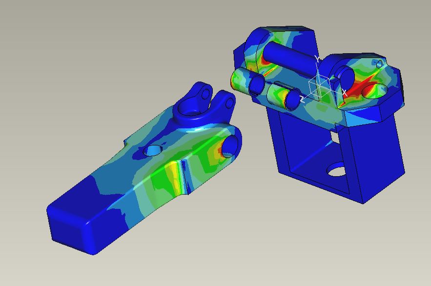
I created some constraints and I am struggling to get the correct results, or should I say what I think should be the correct result.


1.JPG

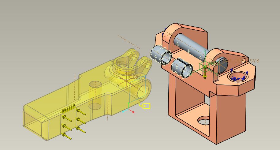
As you can see above, I created a rigid link between the Pin, Bushes and the Arm. I really wanted to create a pin but for some reason I could not get the results correct either.

What I was expecting to see was some load going thru the pin, but I don't see any?

2.JPG

Any ideas or help ? much appreciated.

Cheers

Chris

    Best answer by JonathanHodgson

    Is there a particular reason for analysing the parts as an assembly? As a first pass, just apply appropriate loads to each part individually.

    If you are looking for the effect of, for example, pin deflection changing the load distribution on the arm holes, then I think ultimately a contact analysis is probably the way to go. The WL approach could work but will require careful modelling, for example to split the surfaces to avoid applying 'tensile' loads, and to iterate the spring stiffness to give the right results.

    Given that you will need the bushes for contact, this looks moderately complex and will require a methodical approach to setting up. One thing to watch out for is under-constrained components - you may well still need to use some WLs and springs to prevent free rotation of the bushes and of the pin, for example.

    Give it a go, and post back here if you get stuck!

    1 reply

    13-Aquamarine
    March 27, 2015

    How many rigid links have you created, and what geometry is each one attached to?

    Rigid links are exactly that - rigid - so they will transfer all the load between surfaces they connect, and if they 'bridge' a component then that component will not deflect at all - hence will see no load.

    You could use contacts, or you could use a pair of Weighted Links plus a spring for each pair of surfaces. The key question is which parts of the assembly are you looking to analyse? Are you interested in bush surface pressure, or component stresses away from the holes? If the latter, I wouldn't even include the bushes in the model...

    chutcheon1-VisitorAuthor
    1-Visitor
    March 27, 2015

    I did think about deleting the bushes.

    I was looking to analyse the arm, pin and the holes.

    When I put in the contacts I got an error but I probably could have persevered a bit more.

    13-Aquamarine
    March 30, 2015

    Is there a particular reason for analysing the parts as an assembly? As a first pass, just apply appropriate loads to each part individually.

    If you are looking for the effect of, for example, pin deflection changing the load distribution on the arm holes, then I think ultimately a contact analysis is probably the way to go. The WL approach could work but will require careful modelling, for example to split the surfaces to avoid applying 'tensile' loads, and to iterate the spring stiffness to give the right results.

    Given that you will need the bushes for contact, this looks moderately complex and will require a methodical approach to setting up. One thing to watch out for is under-constrained components - you may well still need to use some WLs and springs to prevent free rotation of the bushes and of the pin, for example.

    Give it a go, and post back here if you get stuck!