12-Amethyst
September 1, 2016
Solved

Chamfer with size related to another edge

  • September 1, 2016
  • 2 replies
  • 8085 views

Hi,

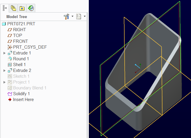
I have two square tubes that need to be welded together with an angle of 90° and with each of them cutted at 45° (as in the picture, hoping it is clear enough):

4.png

and in order to do a proper and completely filling welding, I need to prepare the edges with a chamfer on the ends of both tubes (like a V-Butt weld indeed).

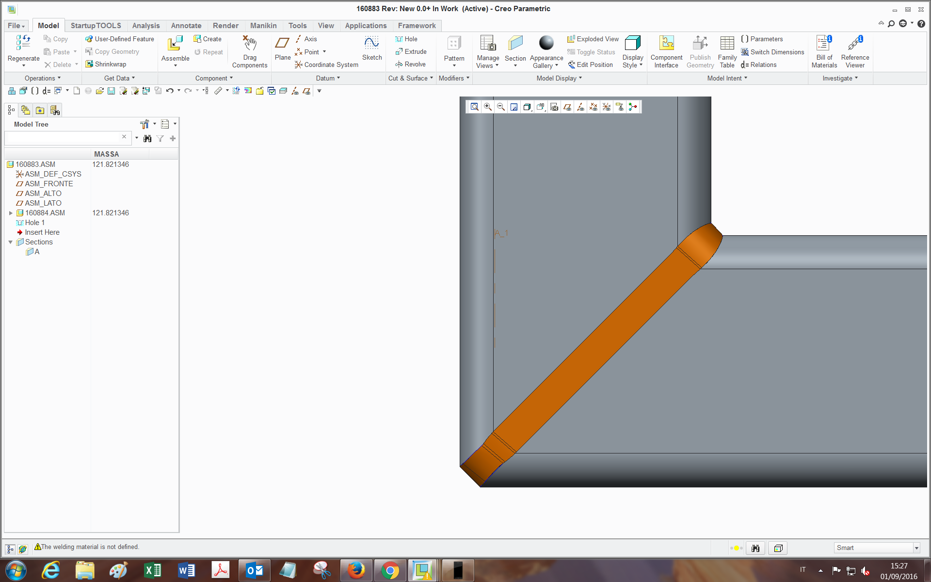
If I just make a chamfer feature on the edge, being it with a constant size, the chamfer doesn't remove material in the same way through the whole edge loop (leaves some flat surfaces, and the reason is related to the geometry).

I am searching for a way to have the white square end of the chamfer being tied everywhere to the inside edge, which would be perfect for my purpose.

3.png

I have tried many ways: selecting reference instead of value, by performing a sweep with the two chains and changing the options (normal to trajectory, to surface, etc etc...), but with no success.

Maybe with the sweep is feasible (and I may be missing something). I would like to avoid the edge prep feature of the welding (admitted it can do this), since it has created problems in the past and I also need to have the feature present and editable in the tubes .prt for manufacturing reasons.

Also, I could find a workaround but as far as I am able to, it has too many features and gets heavy in assemblies.

Has someone already achieved this or knows how could I do?

Many thanks,

Bye


This thread is inactive and closed by the PTC Community Management Team. If you would like to provide a reply and re-open this thread, please notify the moderator and reference the thread. You may also use "Start a topic" button to ask a new question. Please be sure to include what version of the PTC product you are using so another community member knowledgeable about your version may be able to assist.
Best answer by TomD.inPDX

This one uses Offset and Boundary Blend.

Constant offset at 1T.

Check the boundary blend options in the attached file.

The way the two profiles join is manageable in the control points (piece to piece works well here).

Creo 2.0 commercial version attached.

2 replies

17-Peridot
September 1, 2016

You might try a sweep rather than a chamfer.

You can also try trimming the outside surface and blending it back with a boundary blend.

Like everything Creo, there are a number of ways to get to a desired result.

One problem is that one side is already at 45 degrees.

The transition is not as straight forward as you would like it to be.

The sweep feature will show you some of the pitfalls.

17-Peridot
September 1, 2016

This one uses Offset and Boundary Blend.

Constant offset at 1T.

Check the boundary blend options in the attached file.

The way the two profiles join is manageable in the control points (piece to piece works well here).

Creo 2.0 commercial version attached.

tleati12-AmethystAuthor
12-Amethyst
September 2, 2016

Hi Tom,

thank you very much for your replies, indeed it's pretty much what I was hoping for!

I didn't know about some of the options inside the features.

Also, by watching a bit inside I found that:

-The boundary blend turns out less twisted if I select Control points -> Fit: Piece to Piece;

-The solidify can be done also with the remove material option and flipping the direction: at first seems to be digging inside the tube, but after confirmation it's all solid. (Also because I didn't get well the function of the third icon (the one you used)..)

If in the boundary blend I may want to select, as outer chain, isn't the tube inside edge (green in picture):

5.png

but another chain obtained offseting from this one by (let's say) 1 mm, do you think it's feasible by using project feature?(as far as I tried, didn't work out).

thanks

Bye

1-Visitor
September 6, 2016

This version is done using variable-section sweep - advantage: just one feature:

prt0721-USING_sweep.png

(Creo 2.0 model attached)

tleati12-AmethystAuthor
12-Amethyst
September 9, 2016

good alternative, hadn't thought it was properly feasible with sweep...in fact I saw you selected "normal to projection"->TOP plane.

The only limit is that If one wants to leave a plane area for beams contact before welding, the area doesn't come out as plane everywhere around the loop:

1.png

1-Visitor
September 9, 2016

Well, there's a way to do it, though it takes more features:

prt0721-USING_sweep2.png