

Threadmill expertise needed, NPT
I am trying to implement thread mills into Creo negating the need to use a code generator from the manufacturer, so that code can be reliably posted from the manufacturing model.
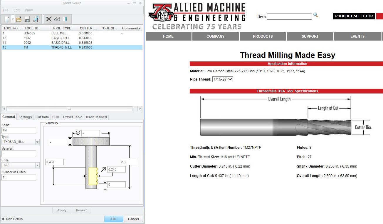
- I am having troubles setting the depth of the NPT, as there seems to be no "thread length" in the parameters, or depth option. I am not completely sure, but this depth appears to be controlled by entering the number of teeth on the cutter, in the "flute" field of the tool information. This seems like a very odd way of controlling depth, is it how it is done?
- The code generated when doing an NPT thread mill is many lines of point movement rather than a few lines of canned cycle. There is no G03 movements output at all, and this makes for a very awkward and VERY long program, any workarounds?
- Placement of the thread when choosing start and end. I am having problems with the placement of the thread, I have attached screenshot to help explain.
In this demonstration, I have made a sample part that is .500 in. thick. I will try to thread a 1/8-27 NPT into it.
Here you can see my how my tool is defined, it is an Allied TM27NPTF in case anyone wants to spec it out further.
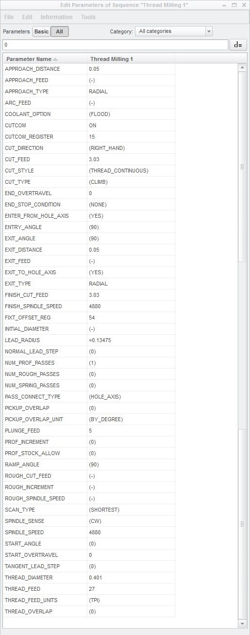
Here are my parameters
I want a normal NPT from the top of the part down, but here is the resulting tool paths that I get. This is with start and end both set to "auto"
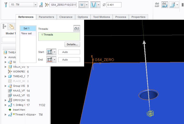
Here I selected the top of the part for start, and left the end as "auto", it gives me the same results as when both on auto. Note that if I try to select the bottom of the part here as the start, and leave the end on "auto", it removes the tool path
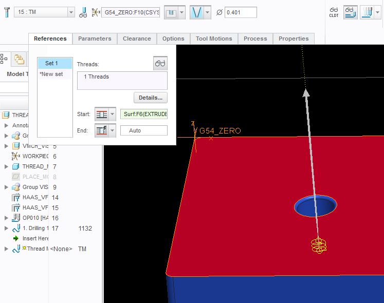
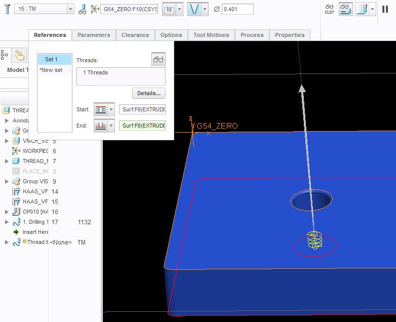
Here the start is still set to the top of the part, but now the end is set to the bottom of the part, yet the tool path is at the bottom and does not complete the thread to the top of the part.
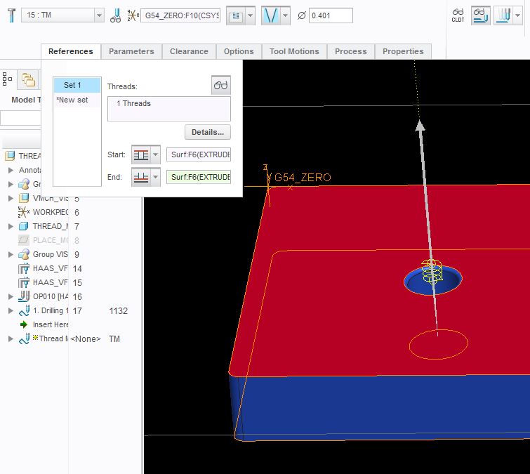
This is the same as above, only reversed. So the start is now set to the bottom of the part, and the end is set to the top of the part. Now the tool path is to far above the part.
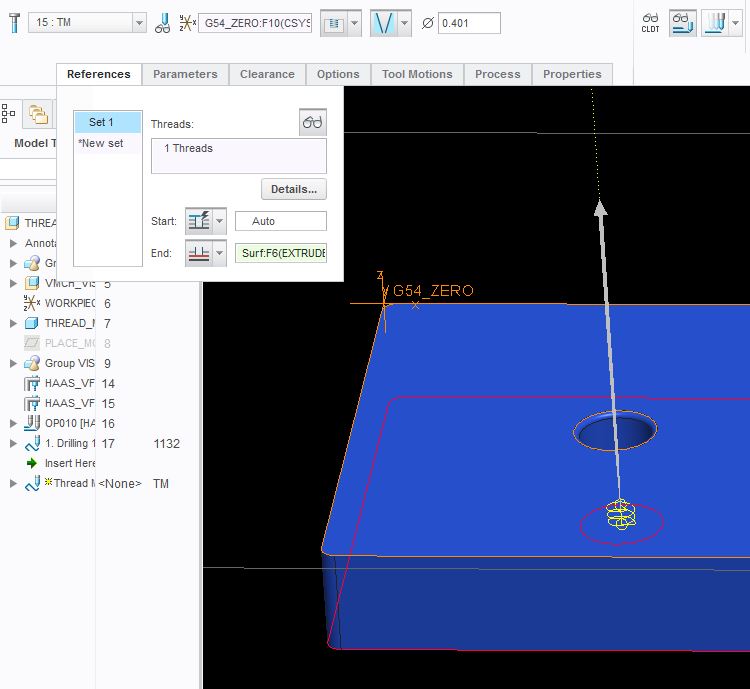
Lastly, we have the start set to auto, and the end set to the bottom of the part. Note that if I try to select the top of the part here as the end, and leave the start on "auto", it removes the tool path.
So aside of putting both start and end to the top of the part, or the bottom of the part simultaneously, I have now exhausted all possible combinations without achieving a normal NPT tool path. I should also mention that I also tried calculating the NPT depth and creating a plane at that depth, setting the "end" to the plane I made, but it still did not make the desired tool path.