12-Amethyst
December 7, 2016
Question

Mapped mesh and conflit with native Creo geometry

  • December 7, 2016
  • 2 replies
  • 3715 views

Hello all


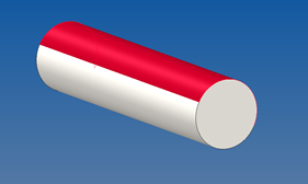
As far I know, since beginning of Pro/E, a CAD volume has been always a โ€œdividedโ€ surface. An extruded (or other construction) part will always have two faces that can be selected.

Usually โ€“ but not always โ€“ most of the time the CAD interprets it as a unique surface. Thus this is not a major problem.


However I have some times meshing problems exactly  in the interface of these surfaces  - especially if it is located in a bad position in an assembly forming for example a sharp corner.


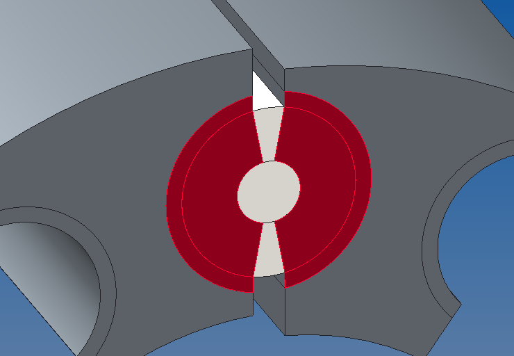
My current issue is that my mapped mesh is getting too complex due to this characteristic. Iยดm trying to create a mapped mesh in a contact region. However this native split is being considered inside Simulate and the consequence is that I have to mesh a more regions and even worst โ€“ to create more contact regions. I consider a good contact mesh a mesh that has common elements in both sides of the contact. This is usually possible only if the mapped mesh patter can match both sides of the contact geometry - as in the picture below when volumes in both sides were create to match the contact region. The problem is that Creo finds not 2 volumes in the cylinder but 4 - due to the native CAD split.
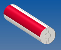


_ My question is if there is a way to โ€œtrickโ€ Creo that it ignores these artificial regions created in the native mode and simple respect the volumes regions that I applied. To illustrate here is the cylinder model. To map the ring I need to map not 4 regions but 6 regions!

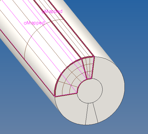
I guess that one can find a good approach for specific cases as the one above but the true is that this undesired split in the original CAD model can cause meshing issues and Iยดm thus looking for a way to merge the native surfaces - if this is the best approach, of course.


Thank you in advance for any feedback.


R. Rabe

2 replies

1-Visitor
December 7, 2016

cylinder / test for mesh

rrabe12-AmethystAuthor
12-Amethyst
December 7, 2016

Thanks Paul


Indeed I have not included all the tries in the original message but basically focused on the main problem - the undesired face split and if there is a way to merge them.


I alreaedy used this approach (placing the native split in the region that has no contact). At least there was a way to mesh the contact region - for this case!

It is better but not free of drawback .


Now I ran into new problems in meshing the non-mapped volumes because the native split part was still causing problems.


To try overcome some bad meshing problem I had to divide the cylinder in even smaller volumes. This was not only more complex but also created a lot of unnecessary elements in a region of less interest (the non-contact).


An additional negative point is that I have to mesh several of these cylinders with contact and each one would have12 volumes to apply mapped-mesh!


rrabe12-AmethystAuthor
12-Amethyst
December 9, 2016

Maybe a nice update.

Although you cannot avoid that Creo always split a part it is possible to โ€œmove itโ€ to a more desired region just segmenting the original sketch.

The original cylinder was dived in the regions that will not have contact. The circle has now 4 controlled segments.

The same procedure when creating the "volume regions" inside Creo Simulate

Now there is no extra regions caused by the native split. The result is thus an easier meshing with less steps (4 regions with mapped mesh).

To guarantee a symmetric meshing in the center a "hard curve control" autogem was included using an axial center line.

1-Visitor
December 9, 2016

Hi,

You wrote: "I consider a good contact mesh a mesh that has common elements in both sides of the contact"...

In simulate (p-system) it is not so, but h-system.

Regards

Paul

rrabe12-AmethystAuthor
12-Amethyst
December 9, 2016

Hi

In some simulations having contact I try to play with the mesh (as using mapped mesh) to try to reduce the solution time or better results around the contact area. Sometimes with good results but a lot of time with non-convergence at all  - although the default (and nearly chaotic) mesh can reach! Still a lot to learn here.

Matching the mapped mesh in both sides of the contact would be for me similar what the option "create compatible mesh" would do in contact with the default mesh. So I though that it is a good way to start. I also saw this approach in some tutorials examples dealing with contact (as you may have already seem is some of the SAXSIM or PTC presentations)

Indeed with a p-system this should be irrelevant but benchmarking two approaches (compatible mesh or not) could show if there is any relevant difference.

I may try IF I finally get my model working with mapped mesh...