16-Pearl
April 27, 2016
Question

[Sheetmetal] Points on a wall and unbend

  • April 27, 2016
  • 4 replies
  • 5628 views

Hi all,

Here's a problem I have on sheetmetal. I have drawn a sketch containing points on a wall. When I unbend the points remain in the same place and don't follow the wall.

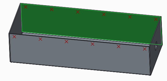
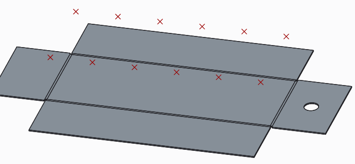
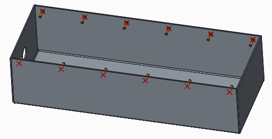
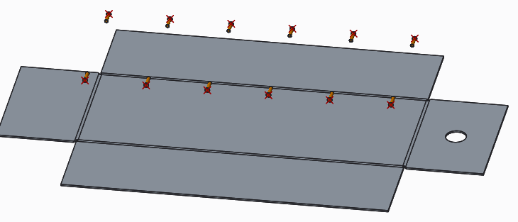
The problem is that I have welded studs constrained on this points, and I would like to do a drawing for the workshop showing the welded studs on the flat part.

Any idea ??

As a workaround, I think of doing a second sketch on the flat part and assemble the studs on it...


This thread is inactive and closed by the PTC Community Management Team. If you would like to provide a reply and re-open this thread, please notify the moderator and reference the thread. You may also use "Start a topic" button to ask a new question. Please be sure to include what version of the PTC product you are using so another community member knowledgeable about your version may be able to assist.

4 replies

21-Topaz II
April 27, 2016

Don't weld studs usually have either a thru hole or a pilot hole to locate them? If so, you could put the holes in walls, then they would be in the flat pattern. Of course, I don't know what type of studs you are planning to use, but that's my suggestion.

RaphMORIN16-PearlAuthor
16-Pearl
April 27, 2016

No, in fact they don't need a hole. We weld them with a cnc machine. They look like below and are designed to be weld on a flat surface.

17-Peridot
April 28, 2016

What if you moved the points to a unfolded state. do they fold back?

I've done a little in this regard and sometimes things move with and other times they don't.

There has to be some logic to it.

I would recommend you create a support case if you can.

Quite often I've had very qualified technicians explain a lot more than I'd ever gleaned from this forum.

Another thought is to place holes and then refill them.  These holes provide axes which can be used for the studs.

1-Visitor
April 27, 2016

We use very small shallow blind holes in this case, then either assign a marking tool in our CAM software for punching, or etch the circle for laser cutting. One can use the hole tool or make a extruded cut with the "remove material normal to surface" deselected.

RaphMORIN16-PearlAuthor
16-Pearl
April 28, 2016

Thanks James for the workaround. I made small shallow blind holes and constrained the studs on them. It works fine now.

I open a case to see what PTC says.

kdirth
21-Topaz I
21-Topaz I
April 28, 2016

That is how CREO works.

Another work around is to make points in the flat state also.  Then in the assembly assemble a second set of weld studs with the part flattened.  You can then use simplified reps to show the assembly correctly in both states.

There is always more to learn.
10-Marble
April 28, 2016

Why not just assemble the studs directly to the part without any points or axis and pattern to suit what you need, it's easier to change positions because you go directly to the part instead of rooting through the model tree to figure out how they're constrained. IMHO....just another way to do it.

Capture1.PNG

Capture2.PNG

Dale_Rosema
23-Emerald III
23-Emerald III
April 29, 2016

Didn't know if the solution from this thread would work here too:

sketch on sheet metal surface

17-Peridot
April 30, 2016

Nice find, Dale!