

Solidify/Cut issue in Creo Simulate containing an assembly with pattern
Hello all
I “suspect” that the command Solidify or Cut is not behaving in well in an assembly containing pattern inside Creo / Creo simulate. So far there is no explicit restriction when using it.
As we know solidify/cut is very useful to explore symmetry in FEM to reduce computing time. Especially in Creo solidify is a good approach if your model contains components having volumes regions to be used inside the simulation. From my experience it is easy to “lose” these volumes made in the CAD parts when you have an assembly that was cut using extrude/revolve feature – but this is another case…
The below assembly (4 CAD parts) was also made patterning some sub-components.
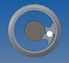
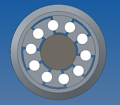
When I try to simplify it using the feature "solidify" (fig. a) the result is bad. If instead I create a volume to cut half of the assembly (fig. b) the result looks god – but not once the model is inside Cre Simulate (fig. c, d)!
a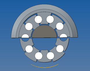 b
b 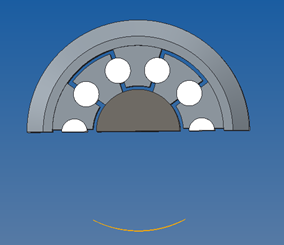
c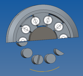 d
d 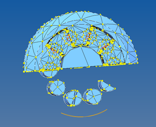
I do not see any logic or restriction why these commands should not work well with pattern. One can argue that since the model contains pattern we can pattern just enough to create the symmetry. This is indeed what I think I have to do in this case but truly it is not the best way since you have to build the model again – what can be very time demand in some cases.
_Has someone faced such problem and found a solution or work around?? I´m using Creo 2.0 M150.
Thanks,
R. Rabe
This thread is inactive and closed by the PTC Community Management Team. If you would like to provide a reply and re-open this thread, please notify the moderator and reference the thread. You may also use "Start a topic" button to ask a new question. Please be sure to include what version of the PTC product you are using so another community member knowledgeable about your version may be able to assist.