17-Peridot
December 28, 2014
Solved

Modeling a globoidal cam

  • December 28, 2014
  • 3 replies
  • 38548 views

Hi all,

what I'm trying to do is the same cam you can see in this youtube video.

I have the motion law I want to assign to the rotation of the tower in function of the rotation of the cam.
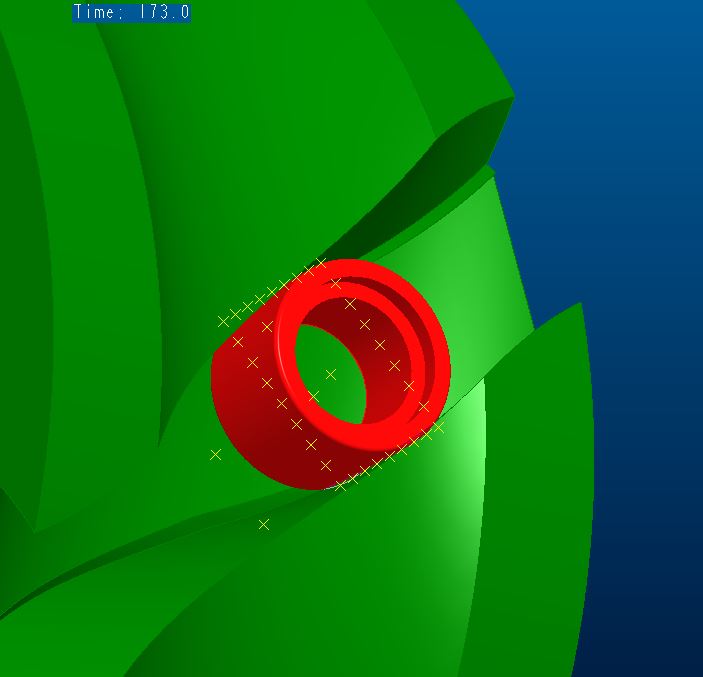
In Mechanism environment, I've made the trace curves of some points of the roller that I've used to cut the cam with surfaces or variable section sweep.
For now, I've tried only one roller cut (three in total).
The cut was decent but there were points where I have interpenetration between cam and roller; especially at the start and the end of the cut.
2.JPG1.JPG3.JPG

So I've thinked that I had to rotate the plane of the roller where I've put the points for the trace curves. The situation was better but the motion law I've assigned to the roller was random: a sinusoidal law, as the main one, that at the half reverses the direction (otherwise the cut plane too on itself).

But, which is the right motion law to assign to the cut plane of the roller?

How would you have done?

Would you know tell me where can I find more detailed informations about this kind of 3D modeling?

I searched on the web, but I've not found nothing if not videos like what I've attached where, however, you can't see HOW to do it.

Thanks.
Bye


This thread is inactive and closed by the PTC Community Management Team. If you would like to provide a reply and re-open this thread, please notify the moderator and reference the thread. You may also use "Start a topic" button to ask a new question. Please be sure to include what version of the PTC product you are using so another community member knowledgeable about your version may be able to assist.
Best answer by gfraulini

http://communities.ptc.com/videos/5576

Remaining in PTC ambit, I am practical with MathCad 15 and Creo 2; but I don't understand this what has to do with the main argument.

Regards

3 replies

17-Peridot
December 28, 2014

It is very problematic creating features such as this accurately. You can confirm this by patterning the revolved shape of the tool along the path. You will see that often, the profile is different.

This is much the same a gear hob. The helix on the hob are flat yet the result is an involute.

Try creating a centerline spline through the profile. Place a point along that curve. Now pattern that point along that curve. Then set the 1st point to along=0. Create a revolve cut the diameter of the groove width. Use the point pattern to pattern the cut. If all went well, the pattern will follow the normal of the spline which also follows the normal of how it was created.

17-Peridot
December 28, 2014

I have attached an example of why there is a difference.

rotating_tool.PNG

This is a comparison with the cutting tool patterned through the groove.

rotating_tool_patterned.PNG

You would have to shape your sweep to make sure you fully remove any interfering material in the cam.

Since this is often critical in the machining operation, you would have to specify the tool path and the cutter diameter to ensure conformance. You will require a small amount of clearance from your guide bearing so it can rotate. It is unfortunate that this is not easy to model correctly as it would be machined. I have been fighting this shortcoming for quite some time in Creo.

Typically we can define the requirements but not adequately represent this in CAD. Milling on a cylinder is just not as cut and dry as many believe. What's worse is that often the feature will fail in the way I have defined this due to accuracy issues. And with Creo 2.0 M040 or earlier, patterns like this fail at random intervals. I am fortunate that this one held up as good as it did.

15-Moonstone
January 8, 2015

respected Giulio fraulini..thanks for ur concern over my problem...i waiting ur tutorial....and also which software u r practical with???

regards

asif

Patriot_1776
22-Sapphire II
January 9, 2015

Interesting, it's like a 90deg version of a Geneva drive.....

https://www.youtube.com/watch?v=HQr4P5WMA-w

Unfortunately, we cannot do solid-body sweeps. That is ONE big area where Solidworks actually has an advantage. This capability is LONG overdue. PTC, are you listening????

17-Peridot
January 9, 2015

We do have motion envelopes which is what SW does. They seems to still be very crude. It also doesn't use the "paper part" method of trace curves. If the two were united, then you might have something.

Overall, this is indeed an interesting subject. I overlayed a swept solid to a thickened solid and ended up with wildly different shapes. One of the major issues here is one that is compounded by the significant difference between the normals of the inside and outside curves. Sweeps can only utilize one. With the reversal, other sweep methods have to be broken up or it will fail. It is yet another mobius problem.

17-Peridot
January 9, 2015

This is the motion envelope for the cam. 112,000 polygons and nearly 30Mb.

Enough to bring my computer to its knees.

In order to get the motion, you have to plan on being able to move the entire mechanism.

motion_envelope_asm0067.PNG

And talk about mobius,,,

mobius_echoes.PNG

I suddenly have a hankerin' for a softserve

gfraulini17-PeridotAuthor
17-Peridot
January 12, 2015

Here it is my files.

I hope that they could explain well what I've done.

17-Peridot
January 13, 2015

With the envelope generation, I can create a very close surface on the inner and outer faces. The problem is the face that counts; where the bearing rolls. It is an involute face.

I will have a look at your file to see what may be resolving inherent issues. It is sort of amazing that it requires a study to solve what is actually simple in real life. But with rapid prototyping on the rise, our software should be able to "easily" recreate real world machining operations.

Below is what I know is accurate, but "facetted". And with Creo 2 M040, patterns are still buggy.

This has been my long time solution to such problems.

cam_steps.PNG

17-Peridot
January 13, 2015

Giulio, thanks for being so persistent with me and providing this file.

I confirmed your findings against the known validation model above.

Indeed, the surface offset method for the walls where the rollers ride creates an accurate roller surface.

The initial sweep based on the two trace curves are all that were required. This appears the only valid sweep as all others seem to deviate due to a twisting action in the trajectory.

I used the offset on the file above and it came out identical (within the graphic limits, obviously).

I then went back to the envelope model I was working with for validation. The offset surfaces from a center sweep did much better than all the sweeps and blends I was able to throw at it.

I also compared the offset to the thicken and when it does not fail, they are also identical. This means that asm0066 above should also be correct (I will review again).

The only difference I found with the envelope model was the bottom of the milling operation. The boundary blend is an approximation. This is no big deal as this is not a functional feature. Just be aware that if milled, it will be somewhat different. I conformed this with a revolve of the mill in the bottom of your cam.

This is the overlay. Very good conformance on the cam surfaces. I could not achieve this with sweeps or boundary blends.

.cam_offset.PNG

Boundary blend approximation of actual bottom milled surface...

cam_offset_mismatch.PNG

This is the difference with the shaded envelope...

cam_offset_mill_end.PNG

This is the mill shape in the bottom of your cam..

What is nice is that this image shows the tangency between the mill bit cylinder and the offset walls.

cam_offset_mill_end_II.PNG

I will see if I can make a motion envelope of you device.

Great work, Giulio! Thank you again for sharing.