Hi Alberto...
I was able to generate the cavity using a couple of different techniques. Neither is really easy to communicate in this format. One method is better if you intend to keep this "core" and update it as your cavity updates. Another is better just for a quick measurement after which you'd discard it.
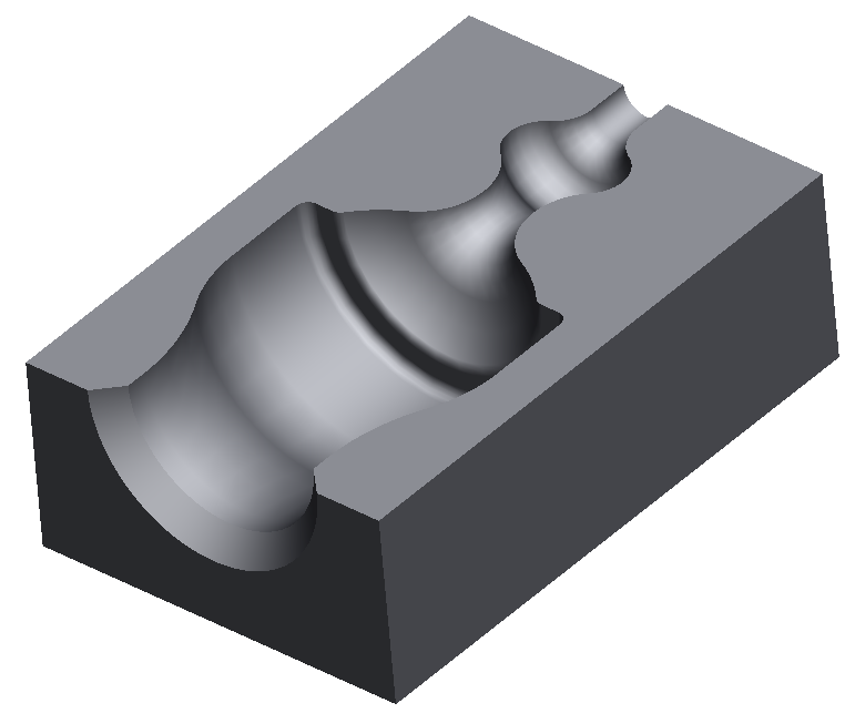
Sample model used for this procedure (cavity model). The procedure is shown in WF5 but is adaptable to Creo, too:
I'll try to describe the process and let you ask questions rather than try to document the steps here. Starting with your original model (I'll call it the "cavity" model):
- Create a new part. We'll call this the "core" model.
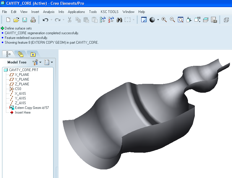
- After the default datums, the first feature of your new model should be a Copy Geometry (External). Load in the cavity model at the default location. Copy all of the surfaces of your cavity bounding the area you wish to calculate. In my sample model below, I copied all the surfaces in red/pink. When this step is complete, you'll have a brand new model that only includes a copy of the pink surfaces- no other geometry.The image below shows the new core model with the external copy geometry feature... you can see the "core" surface, too.
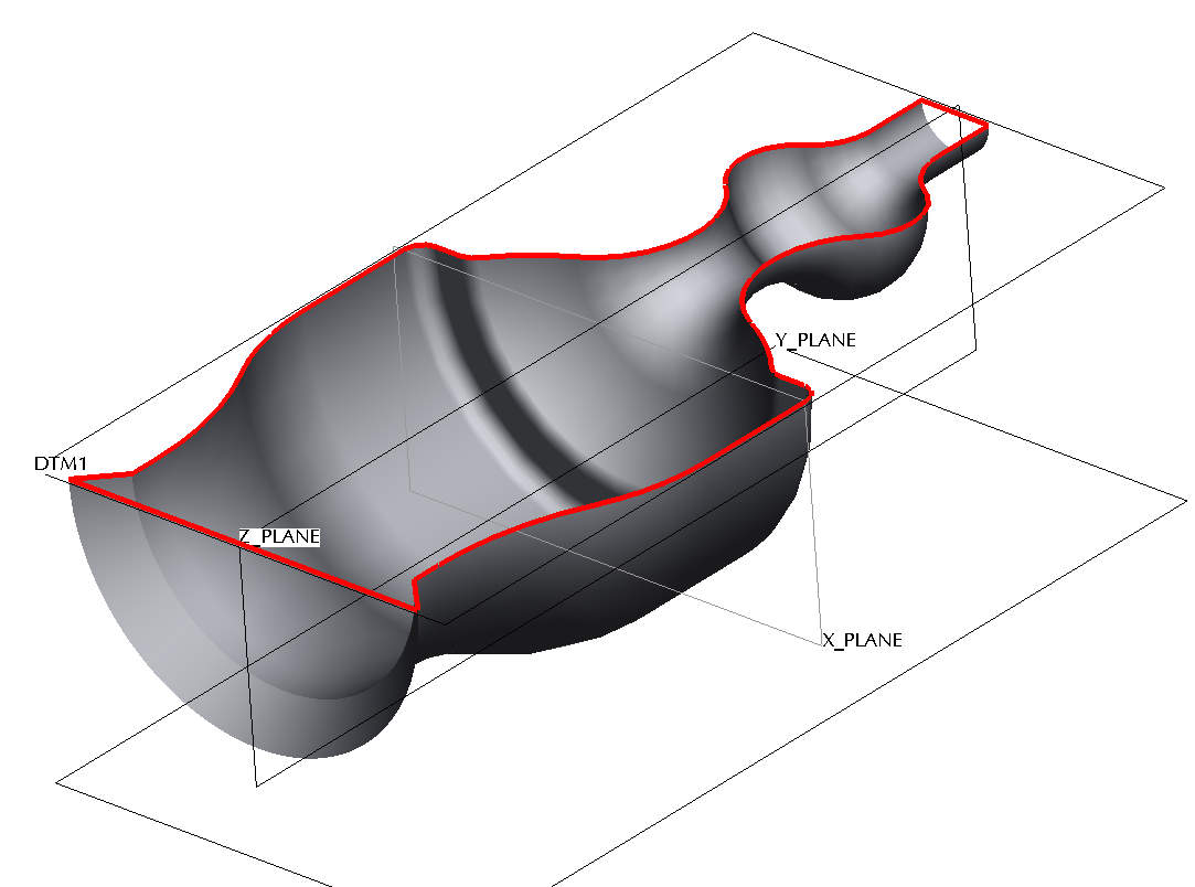
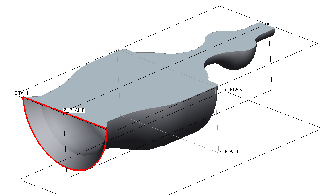
- In the core model, close off the top of the open core using a Fill surface. Start by creating a sketch that follows the curves along the top open edge of your core. Make sure the sketch makes a completely closed loop. Complete the sketch. In the image below, I created the datum plane (DTM1) and sketched the boundary highlighted in red using the edges of the core as references.
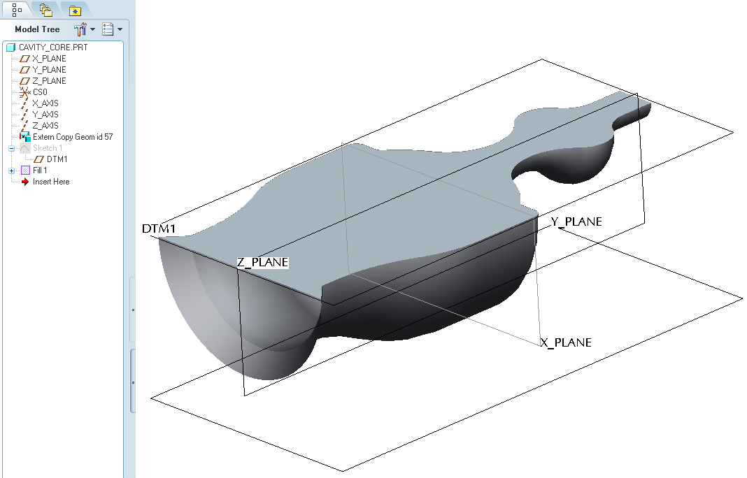
- Select the sketch and then select Edit->Fill to create a filled flat surface from the sketched loop.The top surface will become closed off as shown below. Note the fill feature in the model tree.
- In the core model, generate two boundary blends (Insert->Boundary Blend) to "close off" the open ends of your model. You will need one for each end. You're attempting to create surfaces to "close in" the volume you wish to measure. In the image below, I started by selecting the edges along the open edge of the core (shown in red). Then I simply selected Insert->Boundary Blend and selected the green checkmark to complete the feature. No other options are necessary. Do the same for the other open end.
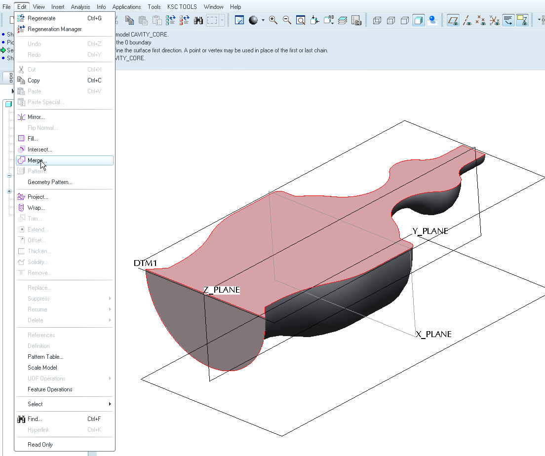
- Merge all of the surfaces together (Edit->Merge). You'll have to merge them in one at a time. As you merge, you'll start to see the surfaces combining (you'll see a mesh-like grid across the combined surfaces that goes away once the feature is completed). In the image below, I started by selecting the two surfaces shown in pink... then selected Edit->Merge.
Next, I selected the surface on the other end... and the merged surface from the previous step...
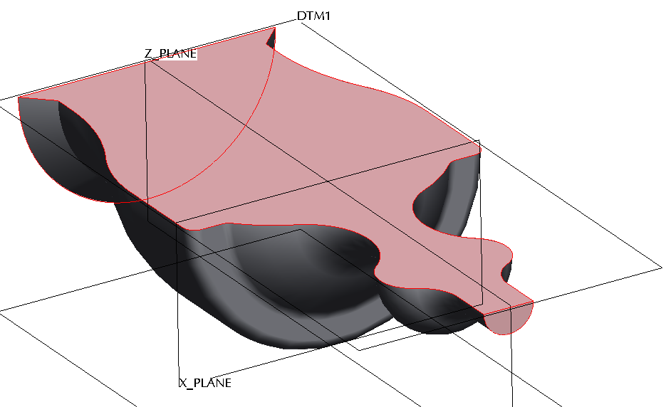
Finally, I merged in the last surface (the complex bottom piece).
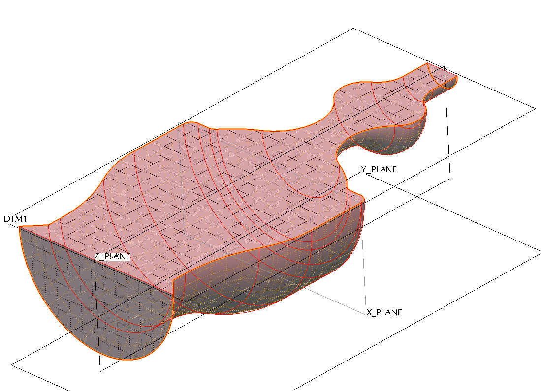
- Once all surfaces are merged, select Edit->Solidify to create a solid volume.
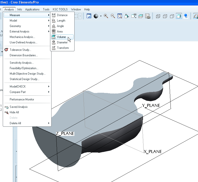
- Measure the solid volume using Analysis->Measure->Volume. As the original cavity changes, you can open and regenerate the core to see the volume update. If you add new curves or sections to your cavity, you may need to do some rework to the core model to insure those new curves are added to your model.
I hope that gives you enough to get you headed in the right direction. There are other ways to do this (assembly cutout) but I like this way better. I'm sure someone else might come up with an alternative but this is how I would approach the problem.
Thanks!
-Brian

