1-Visitor
June 25, 2014
Question

ohNOOO, how do I unbend tubes?

  • June 25, 2014
  • 4 replies
  • 6794 views

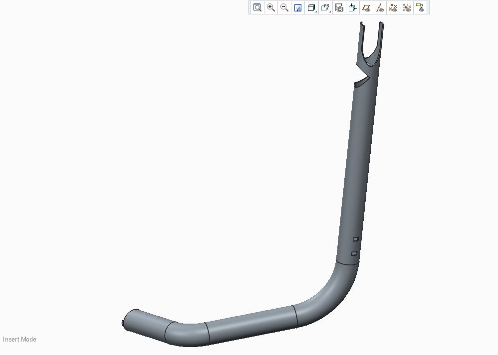
I spent quite some time creating an assembly of round tubes that will be welded together (after they have been lasercut and then bent..). For the lasercutting machine (that reads .stp files) I need to get each tube in an unbend state..

Tried using spinal bend but that only works for bending, not unbending. Any other tricks?

(technically: each tube is a merge of surface-sweeps (extruded and cut) and then added thickness)

How else can one design a 3d-lasercut and bent tube-frame?

Clipboard02.jpg


This thread is inactive and closed by the PTC Community Management Team. If you would like to provide a reply and re-open this thread, please notify the moderator and reference the thread. You may also use "Start a topic" button to ask a new question. Please be sure to include what version of the PTC product you are using so another community member knowledgeable about your version may be able to assist.

4 replies

1-Visitor
June 25, 2014

Can you upload a file we can look at.

1-Visitor
June 25, 2014

Unbending a Tube with Coping at Either End using VTube from advancedtubular.com

http://www.youtube.com/watch?v=J3Iw5puLT70

bp_011-VisitorAuthor
1-Visitor
June 25, 2014

I should think it would be possible with Creo!

Cant upload the original file, but I've recreated a simple assembly with a skeleton and a tube which has the same properties.

thanks!

1-Visitor
June 25, 2014

Given that only one company offers such software, a company that specializes in tube fabrication and inspection software, it's certainly not a common CAD task. It's really a CAM task, one that is usually done after the tubes are formed to minimize compounding cutting tolerances with forming tolerances. Even straight cut-off is most precisely done after forming because of the variable amount of bend allowance and spring-back due to material variations in the raw tube stock. If it's cut on both ends, then pre-bend alignment is also critical as an error there ruins alignment at both ends of the tube.

1) If it is in Creo 3 or a later version, maybe there's the ability to perform a spinal bend on a limited volume of material while retaining all the rest of the part in translation and rotation lockstep to the defining planes, so that the curved portions could be straight.

2) If PTC ever adds a curvature controlled element and the tube was built using it instead of a radius controlled one. Then it would be simple to change the curvature of the bends to 0 and the tube would be straight.

I'd like to see both added to the modeling feature set, particularly to see the spinal bend added to allow assembly features for those parts that are deformed at assembly, such as cables and other flexible materials.

bp_011-VisitorAuthor
1-Visitor
June 25, 2014

Does anyone know if the spinal bend function in Creo 3 might help? I think the tolerances of the laser-cut tube would still be acceptable after bending in real-life, at least I would like to try.. And it looks like Im not going to be able because of software limitations?

17-Peridot
June 25, 2014

That's a great thread, Steven.

Here is another thought, but it gets complex. However, you can play with the K-factor or Y-factor to make up for the distortion through the bends.

I followed the tube with 60.3mm thick sheetmetal. The twist causes a problem in that it untwists in making the end cut. This has to be added -correctly- in a subsequent feature instead. However, you can take data from the master to achieve this.

tube_unbend1.PNG

17-Peridot
June 25, 2014

You might be able to get some tips from the attached full version Creo 2.0 file.

tube_unbend2.PNG

This file is set to the default Y-factor of .5. You can change this to be more accurate.

I used a projected sketch to manage the twist compensation prior to the unbend operation.

be careful with the twist as you have to manually manage the developed length to be equal to the twist length. A relation here might help.

The idea is that you are using the geometry of the initial surface model to create features. You can use analysis to capture values such as 85.0191 degrees, or the location of the final cut. Planes and axes will also provide a lot of valuable references.

Also notice that in the real world, you will have some trouble forming this part after laser cutting the notches and ends. The top end doesn't have enough to grab in the tube bender, and the lower end will likely deform due to the large bit taken out of the material.

Good luck!

bp_011-VisitorAuthor
1-Visitor
June 27, 2014

Thanks for you effort Antonius,

I've given up for now and redesigned my construction into a frame of square tubes which are easily bend/ unbend in creo sheetmetal. Doesnt look as cool but works really well.

I guess you would need a tube-lasercutter with a CNC bending unit integrated in one line to get it done and some suitable software..