15-Moonstone
March 25, 2015
Question

Inaccuracy with Spine Bend

  • March 25, 2015
  • 2 replies
  • 6484 views

This week I tried something that I've been anxious to get to for a long time.

I built my 1st Spine Bend model.

At 1st I was elated, but then I compared the model against the original model which has already proved out with accuracy.

The bend is good with simple rotations but the angles off the "V" shape weave inside and out of the correct position. (The largest error is .075, we need to hold within .010)

See picture of the trouble angles.

Spine Bend.JPG

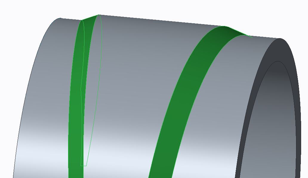
As far as I can tell the angle itself looks fairly good, it's just appears that the "V" position weaves in and out.

There isn't much documentation of what the Options do, perhaps one of these Options might help.

I have watched Leo Greene's excellent You Tube tutorial, but it doesn't hit on what I'm needing to control.

Would anyone know how to stabilize the "V" position on a Spine Bend?

2 replies

17-Peridot
March 25, 2015

You might be seeing an artifact of stretching the material. What if you reverse the spine so it runs on the outside or centered?

For a simple cylindrical bend, you can compare it to a warp feature.

17-Peridot
March 25, 2015

You might also try a curve analysis. Change the part accuracy and you will likely see better results with the analysis as you tighten up the accuracy.

pimm15-MoonstoneAuthor
15-Moonstone
March 26, 2015

I don't believe I'm seeing an issue in regards to the model not being clean. The integrity of this bend looks better than expected. Also, my part accuracy is set more fine than the default value, it is .0005.

Honestly I expected to see variation in the process because of what is being done. How can you maintain rotational and positional integrity on faces that were angled prior to the bend? The mathematics would have to be very challenging by just having a spine curve to bend features that are angled at a tilt.

On the other hand I want to believe there must be some way to add influence to these angled faces to keep them positionally correct.

In our ZW software we are able to get the true angle and position of the angled "V" by using a completely different process. In ZW we build our geometry already rotated. In the early days we discovered that the angled lofts even though they laid perfectly on the drive curve the angles distorted along the drive curve loft. Through the assistance of technical support we discovered that by adding spine curve influence that we could get perfect rotationally integrity on the rotated angled faces.

I know I am doing a completely different process but I'm hoping it is possible to reign in the accuracy.

I'll attach a couple snapshots that show the accuracy deviations.

You can see how the drive angles pull in and out below. I have the original ZW geometry in magenta and the creo geometry in blue.

RollDifferences.JPG

Below is a measurement edge to edge of the difference I'm seeing.

Error Distance.JPG

Patriot_1776
22-Sapphire II
April 3, 2015

One more thing I forgot to mention, is that if that "V" feature is the most important, make absolutely sure the spinal bend curve is the right length (equal to the flat length otherwise it'll stretch or compress the solid - I use relations and a perimeter dimension to ensure that), and it'd be best if the curve used is at the point where the "V" surface and outer surface of the cylinder intersect. A spinal bend will compress (shorten) material on the inside of the curve (essentially the neutral axis) and lengthen in on the outside. Whereas actually bending sheetmetal will pretty much keep the same length on both inner and outer lengths, making the end surface not normal to the spine arc, like it will be with a spinal bend.

pimm15-MoonstoneAuthor
15-Moonstone
April 3, 2015

Thank you Frank,

I had the suspicion that I should be sure the distances matched but wasn't for sure whether this was necessary.

This is good to know.