

CAD Worker Printed Representation different from Drawing in Creo
Hello all,
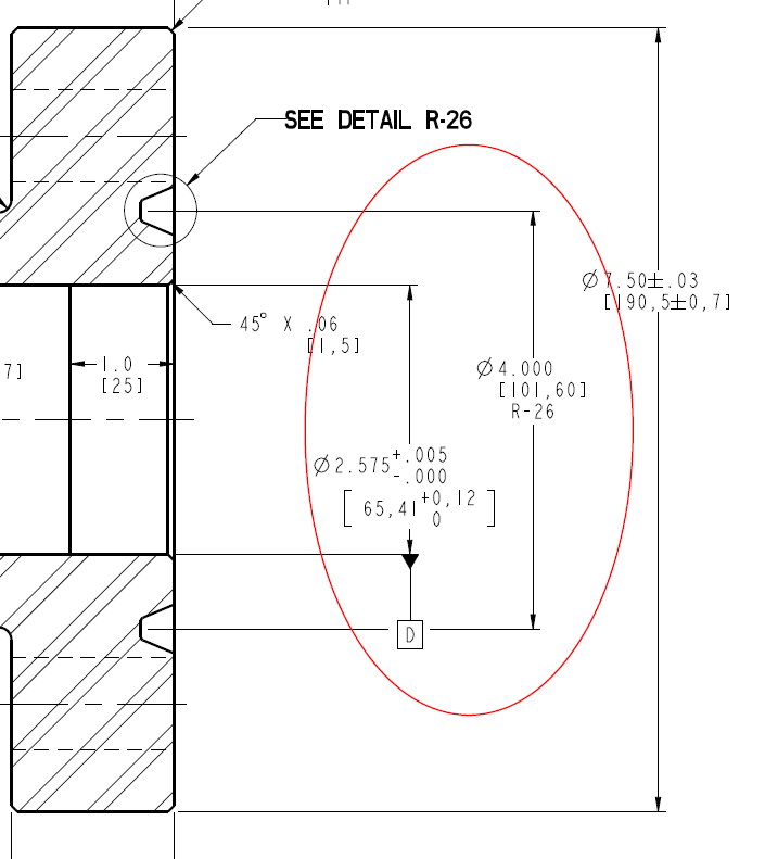
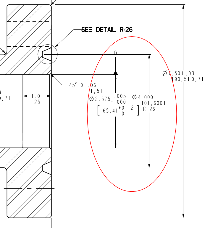
I'm having a hard time figuring out why the pdfs generated by the CAD worker on our Windchill Server are different from the drawings manually printed to pdf from creo. Mostly commonly dimensions are flipped about a center line, but sometimes leaders lines are incorrect, or even angular dimension move! One trick we've found is that if the sketch plane of a feature is perpendicular to the view plane it seems to cause this issue. That is if a feature is sketched on a SIDE plane, but then the dimensions are shown on a FRONT view then those dimensions will often "move" on the printed representation.
I've already gone through all the config files, pentables etc etc that I can think of... Everything is the same between the CAD worker and our standard CREO installs. Does anyone have any other ideas what might be causing this issue?
From Creo:
From the CAD worker/Creoview:
Extra info: We're on Creo 2.0 M120, and Windchill 10.1 M040
This thread is inactive and closed by the PTC Community Management Team. If you would like to provide a reply and re-open this thread, please notify the moderator and reference the thread. You may also use "Start a topic" button to ask a new question. Please be sure to include what version of the PTC product you are using so another community member knowledgeable about your version may be able to assist.