1-Visitor
August 18, 2014
Solved

Maintaining profile orientation along complex path

  • August 18, 2014
  • 2 replies
  • 6508 views

I am trying to sweep a rectangular cut around a 3D profile, and I cannot figure out how to make Creo maintain the definition of vertical. The path is created by intersecting a swept helical surface and an extruded surface.


Capture1.PNG


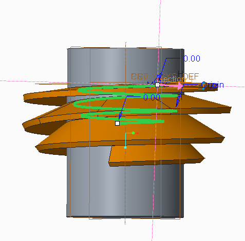
In the image above, I would like the rectangular profile to stay flat as it goes around the trajectory, but instead it is tilting downward. I would assume that the "Horizontal/Vertical control" drop-down in the references tab would let me correct this, but I'm only able to choose "Automatic".


I certainly appreciate any help. I've got 10 year of SolidWorks experience, but only a few days of Creo experience. I'm finding the online tutorials and help inadequate for learning how to create this feature. I'm attaching the model to this post, too.


This thread is inactive and closed by the PTC Community Management Team. If you would like to provide a reply and re-open this thread, please notify the moderator and reference the thread. You may also use "Start a topic" button to ask a new question. Please be sure to include what version of the PTC product you are using so another community member knowledgeable about your version may be able to assist.
Best answer by TomD.inPDX

Welcome to the forum, Greg.

Try making a secondary edge that can be used as a chain in conjunction with the origin or the sweep..

Here is a long cenveration on the subject but David cleared up your problem in the early posts:

Another equation curve approximation error

2 replies

17-Peridot
August 18, 2014

Welcome to the forum, Greg.

Try making a secondary edge that can be used as a chain in conjunction with the origin or the sweep..

Here is a long cenveration on the subject but David cleared up your problem in the early posts:

Another equation curve approximation error

1-Visitor
August 18, 2014

Perfect. Thank you for the help. David's post worked exactly like I hoped.

-Greg

21-Topaz II
August 18, 2014

Another solution maybe to use the "normal to projection" option. This maintains the section plane as normal to an imaginary curve that would be the result of the origin curve projected on the selected plane. In this case, you'd select a plane that is normal to your cylinder's axis.

17-Peridot
August 18, 2014

When used appropriately. Sadly, it is often used as a crutch because the normal to trajectory fails.

I believe a thread cut is an appropriate use for normal to projection.

21-Topaz II
August 18, 2014

Most users that I've talked to don't know the option exists. I've found many uses for it in situations just like this and this is a perfect use for it, it would seem and would eliminate the need to create a second trajectory.