1-Visitor
April 4, 2013
Question

Need help with this revolve

  • April 4, 2013
  • 3 replies
  • 15186 views

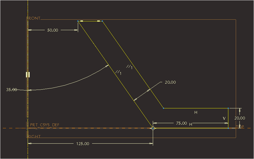
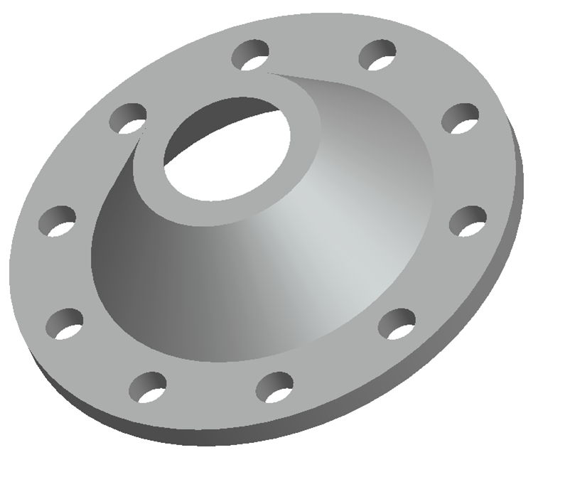
I need help setting up the dimensions and format to look like picture number 1. Then when revolved looks like picture number 2. I know how to the pattern holes already.

revolve1.pngrevolve+2.png


This thread is inactive and closed by the PTC Community Management Team. If you would like to provide a reply and re-open this thread, please notify the moderator and reference the thread. You may also use "Start a topic" button to ask a new question. Please be sure to include what version of the PTC product you are using so another community member knowledgeable about your version may be able to assist.

3 replies

1-Visitor
April 4, 2013

This is on creo parametric 2.0 student.

Dale_Rosema
23-Emerald III
23-Emerald III
April 4, 2013

Start by choosing the revolve icon.

Pick the plane you want to sketch on (Front).

Pick the plane you want as a second reference - typically the right (as shown on your sketch).

Make a centerline coincident with the right axis.

Sketch you shape (don't worry about sizes).

Lock the dimension and change one of them to get close to the dimension listed.

Adjust the rest of the dimension.

Select OK (probably 2x - to get out the sketch and to get out of the revolve.)

Unless you have to have the "dimensions" as shown, typically with revolves, you would (for the 50 dimension) click on the vertex, hold the control key down - click on the centerline made, continue holding the control key, re-click on the vertex, and then click above those points to place a 100 dimension that will straddle the centerline. Do this similarly with the 125 (to get a 250). Then the revole "knows" what your revolving about.

Hope this helps. (do I get the grade too?)

17-Peridot
April 4, 2013

Are you having a problem creating the revolve?

Patriot_1776
22-Sapphire II
April 5, 2013

In WF5/creo, and perhaps also newer versions, you have to make sure the centerline you want is picked and specified in the right-click menu as the axis of revolution. This is a complete pain. This is a step backwards. It used to be that you knew that the first centerline you created was automatically picked as the axis, but you could then change it to be whatever axis you wanted, unlike the versions older than that where the first axis was the only choice unless you deleted the others. I forget to do this ALL the time now in the "enhancement!" that is creo, and it really pi$$es me off. This might be your issue.

17-Peridot
April 5, 2013

Creo 2 is better <cough>, Frank. They actually give you -2- centerlines to insert. 1 is the revolve and the others are reference. That really bit me when I 1st upgraded to Creo.

Patriot_1776
22-Sapphire II
April 5, 2013

Hah! They need to go back to having the first CL default to the axis of revolution, and where you can change it AFTER if you need to. It would save a bunch of time. As it is now, it is SO not intuitive. When I first switched, I thought the command was broken. It STILL bites me. Change for the sake of change, especially when it's LESS functional that the method before it, is retarded....