1-Visitor
December 23, 2012
Solved

TRACING SPIRAL CURVE OR INSERT EQUATION? PROBLEM WITH DESIGNING!

  • December 23, 2012
  • 5 replies
  • 9405 views

Hello!

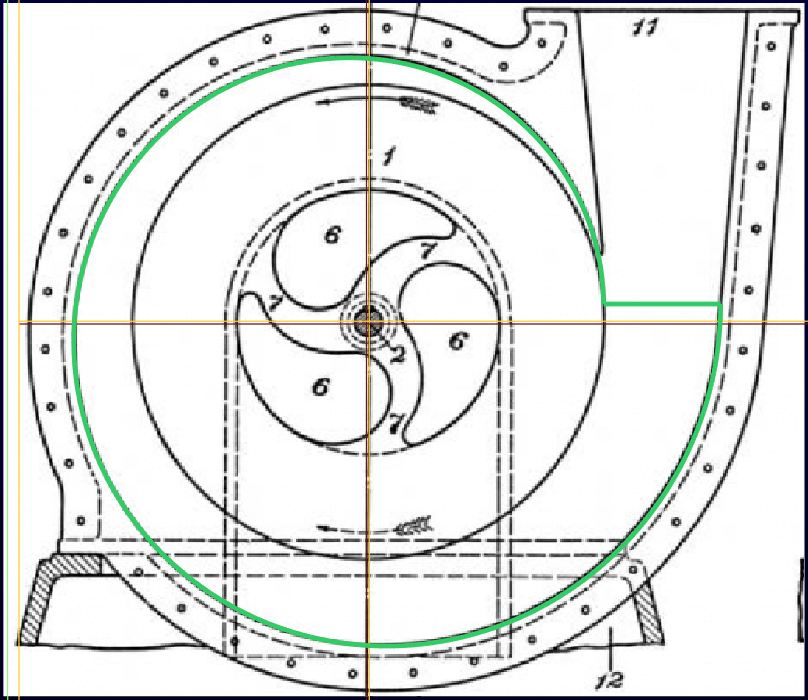
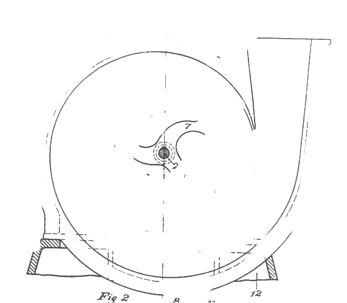
I have spent the last 2 hours, working on tracing a curve from a jpeg image that looks like logarithmic spiral or some similar curver.

Tracing with styling feature cannot give me the accuracy that I need, as the final model will go to cnc for prototyping. (PLS see attached prt)

I would like, to show you this jpeg image and kindly give me your feedback; how to trace or design the curve of the housing with an equation!

CURVETESLA.jpg

a) I have tried with fibonacci spiral and involute curve but doesnt fit to this shape.

b)If is a logaritmic spiral (http://mathdl.maa.org/images/upload_library/23/picado/seashells/espiraleng.html) , I cannot figure out how to insert the equation to Pro E, even to try if it fits. I m stuck here for hours, Please help!

c) I attach the part that came from tracing. As you can see, the spline is not smooth. How can I be sure that if I keep this one part, CNC will not see the joins of the nodes and make sinks on the surface?

Best Regards,

Amanda


This thread is inactive and closed by the PTC Community Management Team. If you would like to provide a reply and re-open this thread, please notify the moderator and reference the thread. You may also use "Start a topic" button to ask a new question. Please be sure to include what version of the PTC product you are using so another community member knowledgeable about your version may be able to assist.
Best answer by TomD.inPDX

oops, forgot. I am on Creo 2.0.

Play with the center some more. If you place the shaft of the drawing at the datum intersection, you will be able to scale the image to fit the curve.

The image I included shows as 20.47 high and 17.71 wide in the image dialog. I had to rotate the image 90 degrees CW. I just duplicated the effort and the values came out the same. The center is located on the default datum plane intersection. Here is a more detailed overlay:

curve_from_equation_III.JPG

I don't think that any equation can fit the original sketch any better. I will again refer to the use of french curves to document to original patent application. It is hard to tell how accurate the original prototype was cast as well. Regardless, the functionality could have been sufficient albeit not optimized.

There may well be a much better profile based on pressures in particular zones. It may not follow this curve at all. Today, most turbo pumps use a common profile that expands in all directions proportionally.

5 replies

17-Peridot
December 24, 2012

1st, I am going to suggest that the image is not exact. Most likely drawn with a french curve as close as someone needed it for conveying the idea. Obviously not perfect for functionality.

2nd, I would suggest you make a proper curve through a complete 360 degrees. You can use the image as an underlay to get "close" but trust the equation rather than the sketch.

3rd, Use tangency, mirrors, and fillets to complete the geometry for the "flute".

..and I learned that images do not carry forward with zipped part files. Using the image jpeg from the post also did not show up. I had to make a PNG and place it to make it work. Not even naming the jpeg properly would show the image in Creo 2.0. Another bug?

17-Peridot
December 24, 2012

Turbo_curve.JPG

This is a poor man's version of the turbo curve. 8 points at 45 degrees on equally spaced concentric circles and tangent ends on the spline.

1-Visitor
December 24, 2012

Antonius Dirriwachter,first of all thanks so much for your prompt and helpfull reply !

1. I didnt knew about jpeg and png matter. I will convert the image as well. This silly image is the only thing they gave me and they insist on designing the basic casing of this turbo based on this specific image. I will use it as a reference only for comparing my results.

2. I like your suggestion with concentric centers and 8 points. How much bigger gets the diameter of each circle ?

3. The flute of this turbo I think is the easiest part, as it seems to be tangent to the very outer circle. Right?

4. If we assume that this turbine shape is based on a mathematical spiral curve, is this the Logarithmic one? AND if yes, I want to try inserting the equation, but since I am a newbie in insering equations, I cannot find the way I should write the equation for Pro E. Does anyone knows how to ? ( here in this community, I can find too many other equations except this one )

Thanks again for your feedback.

Looking forward to more suggestions!

24-Ruby IV
December 24, 2012
1-Visitor
December 24, 2012

Thanks for your reply; however, I dont need to trace from the picture, but to figure out the equation of the curve so as to have continuity = 0 at bezier splines!

17-Peridot
December 24, 2012

Answer to 3. is that you can make the flute tangent to the spline.

You might have to ask the mathmatica guys how to read in a curve equation. Certainly not a strong point for me. I like letting my geometry do the work. But it is clear your assignment wants you to find this information.

flute.JPG

I can never find how to import data in Creo when I need to. Not even sure you can import the curve directly from an equation, of if you have to create the points and then create the curve. If you fit the curve to points, be sure to set the spline end conditions.

17-Peridot
December 26, 2012

In case anyone else is following this, have a look at Tesla's original patent on this pump:

http://www.teslauniverse.com/nikola-tesla-patents-1,061,142-fluid-propulsion

1-Visitor
January 2, 2013

This this the original source of the drawing. However, the project goes much further than this based on that jpeg photo.

1-Visitor
January 2, 2013

Trying to align the photo (playing with scale) with the datum curve - from equation- I cannot get your result.

The curve made from

r = 6 + t * (8 - 2)

theta = t * 360 * 2

z = 0

give as concentic circles while in Tesla's dwg it is kind of involute or sth....

Pls see below attached .... The datum curve in blue does not match with scaled image . I know that is not a perfect aligment but I can see that no matter moving I do, there is a slight difference in the geometry.

Where I am mistaken?

curve aligment with photo.jpg

17-Peridot
January 2, 2013

I think it is an image scaling thing... I was very careful to scale using the corners so as not to change the aspect ratio. I am sure you did also.

I have attached the part and the image. If you unzip both files in the same folder, it should open properly with the image in tact. I had trouble doing this with your original version. Please let me know if the image comes in by default.

17-Peridot
January 2, 2013

Also unhide sketch 2 and see something interesting with regard to "implied center".

I need to take that idea further and see what I find.

1-Visitor
January 2, 2013

tesla+curve.jpg

You were right!

Now I need to get the details for the flute....As you said , it is just a tangent line ....Reverting with that as well.

17-Peridot
January 2, 2013

It was an interesting problem. Glad I could help.

Happy New Year!