15-Moonstone
November 29, 2012
Question

Trouble with floating sketch constraints

  • November 29, 2012
  • 6 replies
  • 6987 views

I'm having a lot of difficulty in figuring out how to keep the constraints in sketches from floating around. I can go line to line with all the appropriate sketch dimensions but things start to skew when I add a radii. The radii may place correctly initially but the dimensional constraints start to distort. Since I can't just initially place the radii to what ever size I want it requires an additional step of modifying the radii. This modification always makes the other geometry lose it's position. I can prevent the size distortion if I reconstrain the 1st radii's placement, but I already constrained everything prior to the radii blowing away my dimensional constraint.

I will attach the progression that I am frustrated with.

Sketch1.jpg

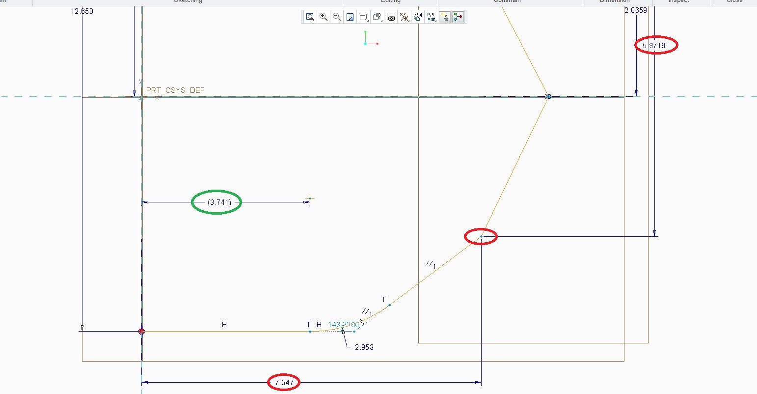
In looking at the above sketch I have things the way I want it. There is a horizontal and vertical dimension placing my position. There is a point at the intersection.

Next; I will need to add my radii.

Sketch2.jpg

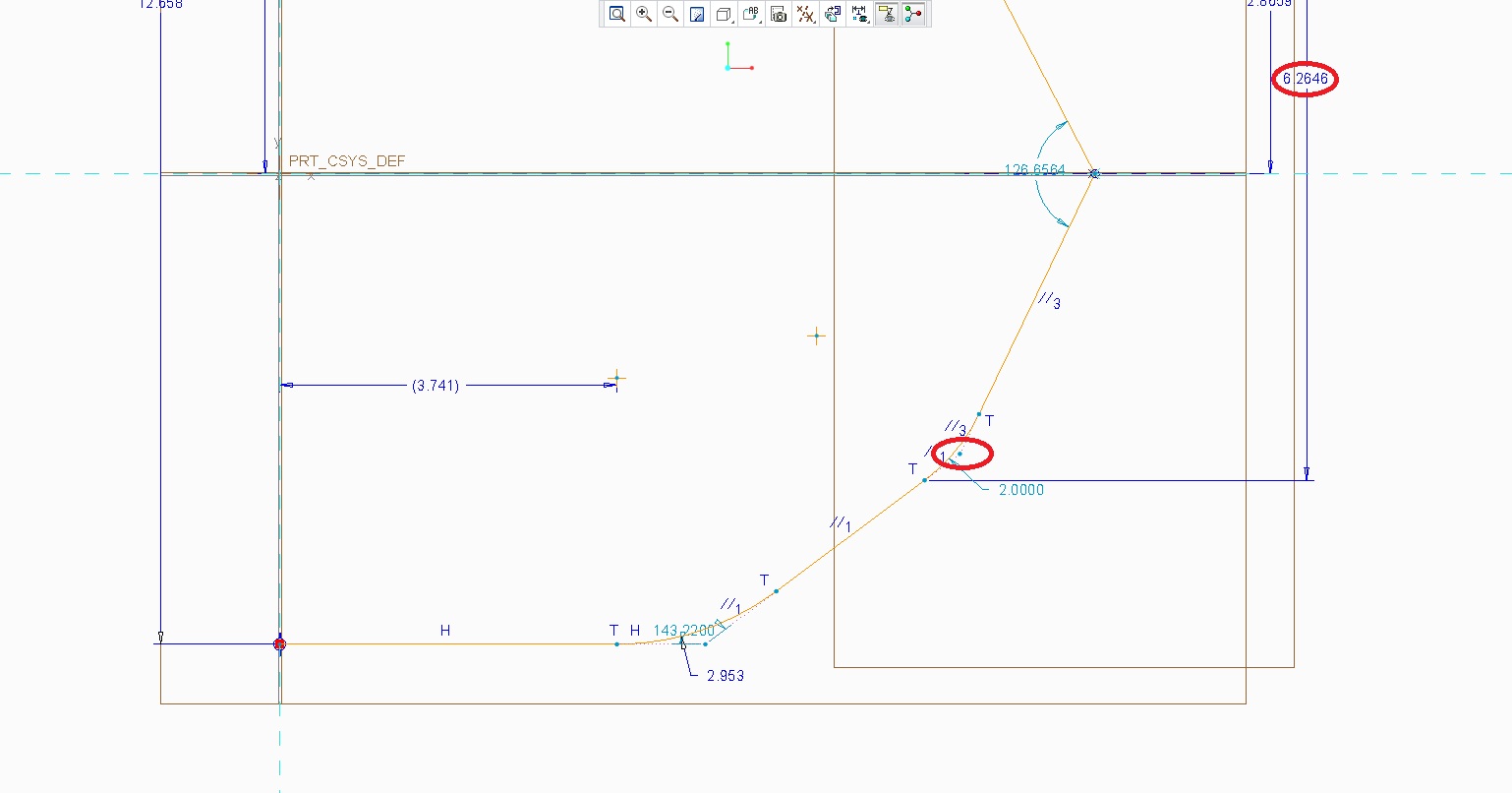
Above you can see my dimension scheme starting to unglue. My horizontal dimension has been removed. The vertical dimension now has shifted to a tangency on the radii I just added. (That doesn't help me at all). Circled in red you can see that the original point which had the horizontal and vertical dimension is still there, but it lost it's 2 strong dimensions.

I'm not done yet; I have to modify the initial radii to the size I actually need.

Sketch3.jpg

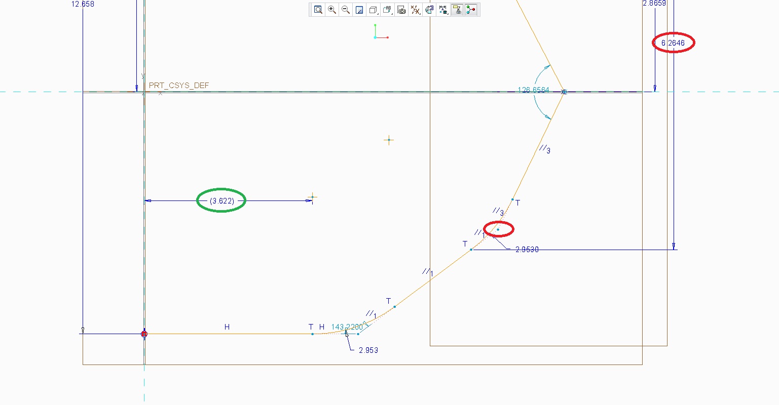
As you can see above not only does the sketch retain the useless vertical dimension it also shifted the placement of the dimension shown in Green.

As I see it there is only 2 choices here 1) have size distortions or 2) add extra steps in reconstraining dimensions that were removed with the radii placement.

I have submitted an idea for not having to double enter the radii, which would prevent some of the problem here. http://communities.ptc.com/ideas/2028

There is another idea submission which addresses the removal of the 2 dimensions with the radii placement. http://communities.ptc.com/ideas/1006

Not too many votes for these submissions which makes me wonder if there is an alternate but less intuitive way of placing the radii.


This thread is inactive and closed by the PTC Community Management Team. If you would like to provide a reply and re-open this thread, please notify the moderator and reference the thread. You may also use "Start a topic" button to ask a new question. Please be sure to include what version of the PTC product you are using so another community member knowledgeable about your version may be able to assist.

6 replies

17-Peridot
November 29, 2012

I find that sketch constraints are becoming dumber with every release. When it shows me the conflicting constraints, it rarely includes the one that is really the crux of the problem.

The upside to your dilemma is that you can start adding your own dimensions where you really want them and the assumed dimensions will go away. Often time, indeed, you cannot make them the value you want until you alleviate the assumed dimensions that get in your way.

Use constraints whenever you can, particularly symmetry about a centerline. Next, those extensions at the fillet radii are optional. If you don't want to use them, you -can- delete them. I find them useful for dimensioning.

Otherwise, yes, it is a pain to get a sketch under control. Often times I have to sneak up on the outcome I want. Silly but true.

17-Peridot
November 29, 2012

...and don't forget that you can stretch geometry around in your sketch. There are setting in config.pro that allow certain dimensions to become hard dimensions that won't change when you stretch the sketch around.

sketcher_dimension_autolock is set to no by default

pimm15-MoonstoneAuthor
15-Moonstone
November 29, 2012

I appreciate your ideas Antonius, unfortunately even locked dimensions don't solve this dilemna.

Sketch+Locked.jpg

As shown above even locked dimensions easily unlock when it comes to placing radii.

You are very right about having to sneak up on the correct outcome.

If anyone is having this issue I've linked in my initial post a couple of related idea submissions.

1-Visitor
November 29, 2012

They always say, if possible don't add radii in sketches but use fillet feature instead. Once the sketch is done.

Sketched curves alone can't be filleted other ways than editting the sketch itself. In case I need a fillet just on the curve, and can't seem to be able to get that using sketcher, I just fill in the sketch with a surface using Fill feature and then use vertex round on the corner of this new surface. Then it's possible to copy the edges of the surface and maintain the whole design intent like they say.

I couldn't think of a better way how to get along with the problem with sketcher fillets.

And yeap, sketcher_dimension_autolock is good but sometimes locked dims also get replaced by weak ones.

I think you should be following this process while sketching:

1) Create the sketched geom

2) Dimension the geom and add constrains according to your needs

3) Select the whole sketch and choose modify

4) While using lock scale you can then change the values of dims as you want

Regards,

~Jakub

Dale_Rosema
23-Emerald III
23-Emerald III
November 29, 2012

Adding fillets in sketch mode typically will get rid of strong dimensions. I typically get the shape in the general proportion that is needed with the fillets that are required. Then add constraints as Antonius noted along with strong dimensions after the shape is done.

1-Visitor
November 29, 2012

One method you could try is using sketch points. Dimension the sketch points and lock those, draw your lines through the points, and then add fillets. Try it and see if it does what your looking for. The dimensions shouldn't change and the fillet should be added with point on entity and tangent constraints.

17-Peridot
November 29, 2012

Good call, Kevin. Indeed the line constraints remain coincident at the points when the fillet is added.

1-Visitor
December 5, 2012

Here is the way I use to do that:

1. Draw your sketch without any fillet:

fillet1.JPG

2. Draw an arc, tangent at both ends:

fillet2.JPG

3. Divide the two staight lines at tangency points:

fillet3.JPG

4. Convert the resulting lines to construction entities:

fillet4.JPG

Done !

pimm15-MoonstoneAuthor
15-Moonstone
December 5, 2012

Thank you for this idea.

This may be a good work around; even though it does add a couple steps of splitting lines and converting the split lines to construction.

How do you create your Arc? I tried the Arc using 3 point Arc but even though a good solution hilights it won't drop. I tried as a tangent end arc, but it only gives me tangency on 1 end.

1-Visitor
December 5, 2012

3 points/tangent arc which is tangent at one end, then add a tangent constraint at the other end.

EDIT: I'm using Creo/Pro 5.0

pimm15-MoonstoneAuthor
15-Moonstone
December 5, 2012

I am very glad that I started this thread as there are many viable workarounds. Every one has it's pro's as well as it's con's.

The con always is that there is extra steps involved in getting what you want.

I certainly would like to see this simple yet frustrating issue put to rest.

There are ideas submitted in this regards. The closest answer to this issue is this link for voting on a change.

http://communities.ptc.com/ideas/1006

I appreciate everyone's feedback!

1-Visitor
December 6, 2012

I agree with the not-needed-time-consuming extra steps.

The idea link does not work properly.