14-Alexandrite
March 3, 2016
Solved

All edges in drawing don't show

  • March 3, 2016
  • 5 replies
  • 5969 views

Hi,


I have a strange problem, and I've encountered it before. In a drawing view with "No Hidden" Display style the edges of some parts sometimes dissappear. See the picture below. If I select the part in the drawing I can seen the outline (green on the right), but it won't show by itself. I've tried with "Display style" Wireframe and Hidden. In these I can see the edges. It seems that the edges are considered behind something, which as seen in the colour image is clearly not the case. Any ideas on solving this? I run Creo 3, M050.
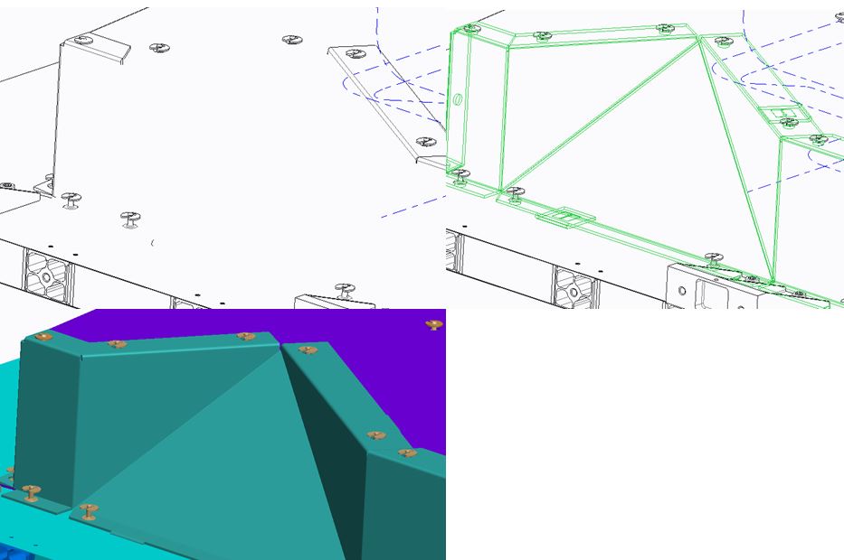
 

Capture.JPG


This thread is inactive and closed by the PTC Community Management Team. If you would like to provide a reply and re-open this thread, please notify the moderator and reference the thread. You may also use "Start a topic" button to ask a new question. Please be sure to include what version of the PTC product you are using so another community member knowledgeable about your version may be able to assist.

Best answer by StephenW

Usually it shows up worse in 3D type (ISO) views. Orthographic views are generally better at working out the line display issue.

We see it all the time with our hardware.

For simple assemblies, I'll make a component flexible and adjust a dimension to eliminate the interference. For complicated stuff, I try adjusting view orientation if I can or just not use the 3D view.

When I used to work with sheet metal (like some of your stuff looks like), I used to hate inserts and what-not that was press fit or deformed fit for that reason.

The work arounds are usually painful, like "eliminating all interferences", creating draft geometry using "project" or use edge.

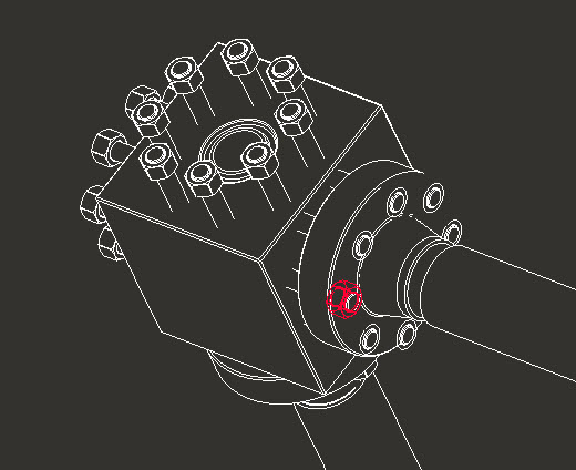
iso-int.jpg

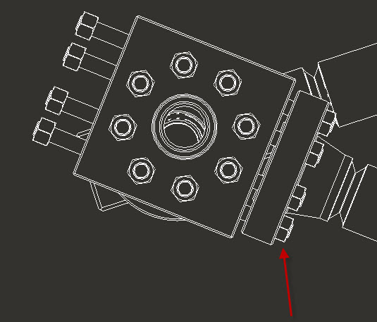
normal-int.jpg

5 replies

StephenW
23-Emerald III
March 3, 2016

Do you have any interferences in the assembly? It's very common to see this when there are interferences, sometimes not specifically in that spot.

14-Alexandrite
March 3, 2016

Well I guess there may be interferences at some points. They do however show again if the view angle is changed.

StephenW
StephenW23-Emerald IIIAnswer
23-Emerald III
March 3, 2016

Usually it shows up worse in 3D type (ISO) views. Orthographic views are generally better at working out the line display issue.

We see it all the time with our hardware.

For simple assemblies, I'll make a component flexible and adjust a dimension to eliminate the interference. For complicated stuff, I try adjusting view orientation if I can or just not use the 3D view.

When I used to work with sheet metal (like some of your stuff looks like), I used to hate inserts and what-not that was press fit or deformed fit for that reason.

The work arounds are usually painful, like "eliminating all interferences", creating draft geometry using "project" or use edge.

iso-int.jpg

normal-int.jpg