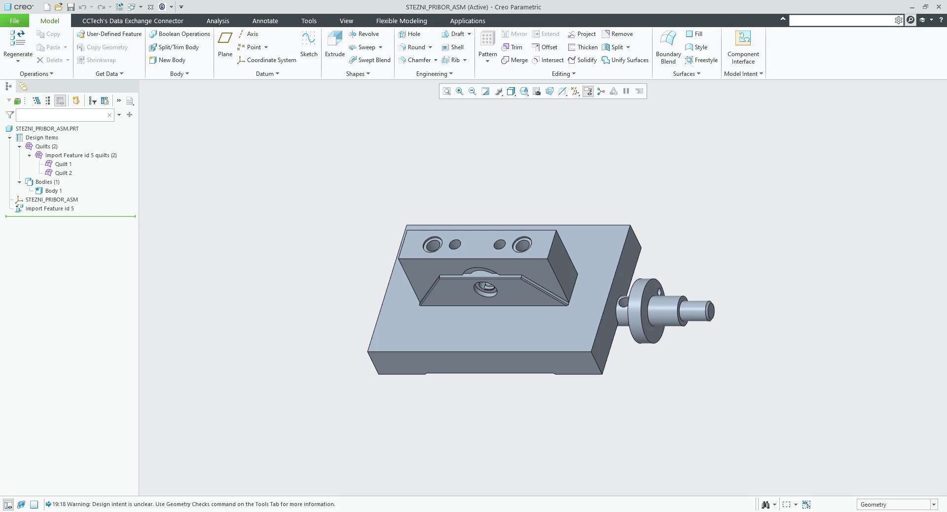
Assembly STEP imported in Part mode — wrong geometry (Creo 11.0.6.0)
When I import an assembly STEP (stezni_pribor_asm.stp) into Creo’s Part mode (File > Open > .stp, Type = Part, Import type = Geometry), the resulting part has wrong geometry: some solids in the STEP file come in as open quilts, some components are missing, and the rest overlap.
Creo reports: Warning: Importing assembly in part mode. Geometry may be wrong.
- WARNING: One-sided edge found in IMPORT FEATURE.
- WARNING: Unattached IMPORT FEATURE was detected.
- WARNING: Unattached IMPORT FEATURE was detected.
- WARNING: Feature creation resulted in overlapping part geometry.
- Warning: Design intent is unclear. Use Geometry Checks command on the Tools Tab for more information.
The same file imported with Type = Assembly comes in perfectly - every solid component comes as a solid, correctly placed. I have attached the step file and screenshots of both imports - the same STEP file imported as a Part, and imported as an Assembly for reference.
Questions:
1. Is Part mode supported for an assembly STEP, or is the geometry expected to degrade whenever this warning appears?
2. Is there any setting - import profile option, accuracy, config option - that makes it import reliably as one multi-body part?
STEP file imported as an Assembly:
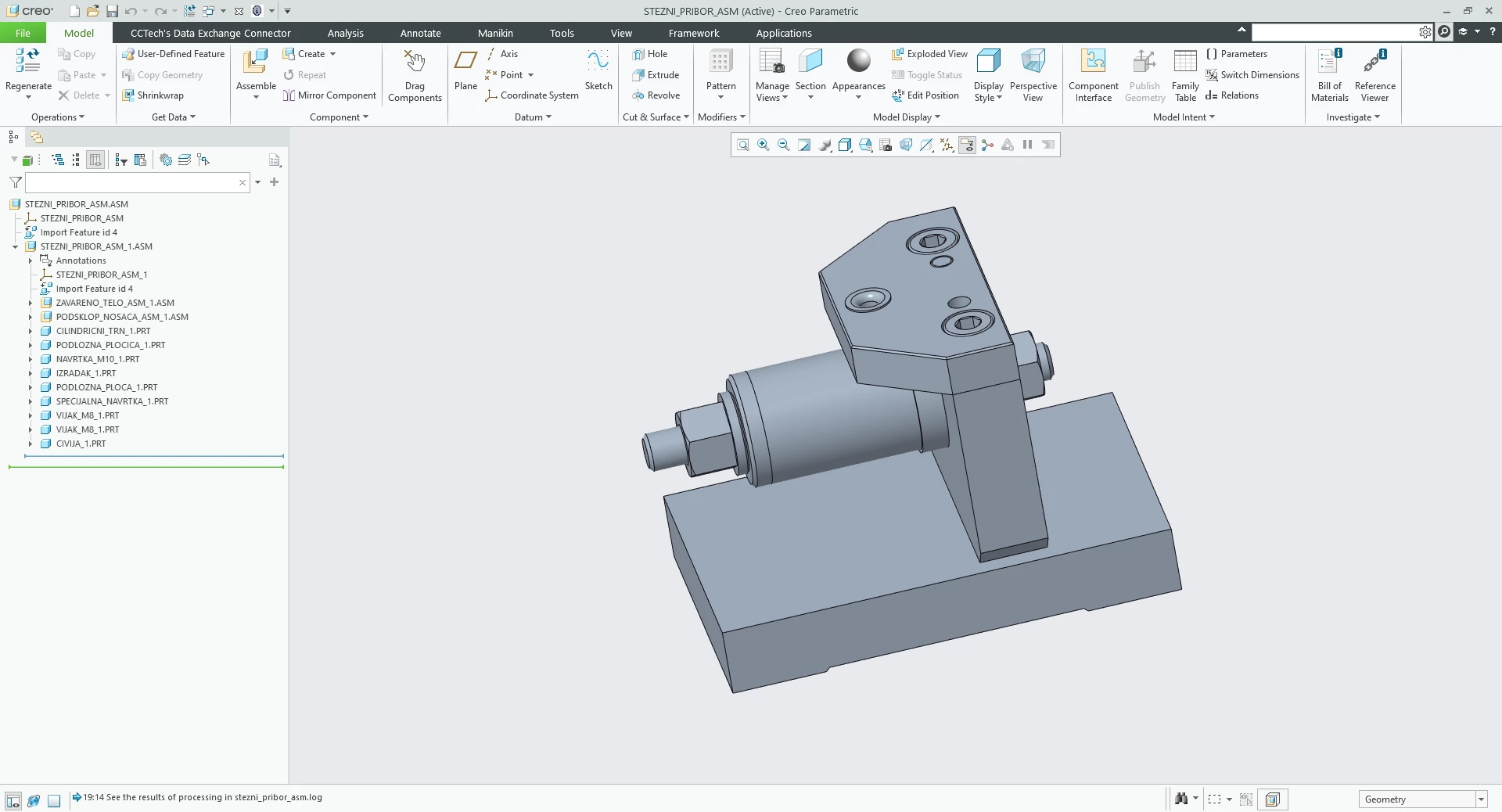
STEP file imported as a Part: