
4-Participant
Sep 11, 2025 10:09 AM UTC
Solved

Ball connection blocking in layered sub-assemblies

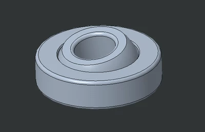
I created an assembly representing a commercial ball joint, called SKF_GE-4-C. This assembly is composed by a housing mounted by default and a sphere mounted with a "ball" connection type. If I drag components, everything is working fine at this level.
Lawproto_0-1757584347955.png

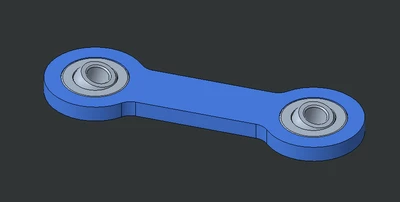
Then I used this file as a component for another assembly called SUB, mounted as rigid. If I drag components, everything is working as expected at this level as well.
Lawproto_1-1757584724390.png

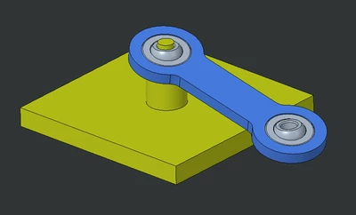
However, when I insert SUB in another assembly called MAIN and try to constrain the hole of the ball with a fixed shaft, everything locks in place. I am not able to move the beam with drag components as I intend to do.
Lawproto_2-1757584910513.png

Is it possible to get it to move preserving the same (or a similar) structure of assembly? What do you suggest?


Using Creo 9.0.9.0. Files in attachment for reference.
pausobAnswer
19-Tanzanite
Sep 13, 2025 1:48 AM UTC

In general, I would avoid the use of the "standard" constraints when dealing with mechanisms.

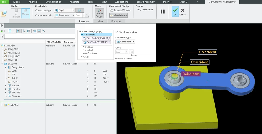
I know that it often works, but sometimes it just gives weird results.  For your situation, try to see if the mechanism works if you re-define the connection between the ball element and the base to be of "Rigid" type:

pausob_0-1757727775876.png

I would also recommend that you fully constrain everything.  Avoid use of the "assumed" constraints.   

6 replies

18-Opal
Sep 11, 2025 8:46 PM UTC

Hi all,


Here are the commercial files for ball-joint-example.zip.


Thanks,

Mark

Translate
tbraxton
22-Sapphire II
Sep 11, 2025 10:27 PM UTC

Watch the video below and respond if this is the desired behavior. The example shown was built using a commercial license after converting your educational files to open in a commercial license.


You must consider the ground body (or bodies) in the context of the mechanism joints. The base in your scheme is intended to be the ground body. If you were to build the assembly from the "ground" up and constrain the ball joints in this context then you will have the kinematic movement available. The SKF housing part will move relative to the ground body which is defined by the base. If you bond the SKF ball part to the ground body, then you can drag the beam through a range of motion.


tbraxton_0-1757628740765.png


Translate
pausob19-TanzaniteAnswer
19-Tanzanite
Sep 13, 2025 1:48 AM UTC

In general, I would avoid the use of the "standard" constraints when dealing with mechanisms.

I know that it often works, but sometimes it just gives weird results.  For your situation, try to see if the mechanism works if you re-define the connection between the ball element and the base to be of "Rigid" type:

pausob_0-1757727775876.png

I would also recommend that you fully constrain everything.  Avoid use of the "assumed" constraints.   

Translate
Lawproto4-ParticipantAuthor
4-Participant
Sep 15, 2025 9:34 AM UTC

I was really surprised to see this simple suggestion working for me. I can now move the beam while keeping the same assembly structure, thank you.


What is the difference between "User defined" and "Rigid" connection type? I have used them interchangeably but now I understand they are different.

Translate
19-Tanzanite
Sep 15, 2025 2:55 PM UTC

Hi @Lawproto, glad this worked for you.  TBH, I have no idea why it makes a difference and what is going on "behind-the-scenes"; I could only speculate that it is something about how the software defines the kinematic loops and assigns the objects to the ground body.  BTW, my brief look for the answer on the internet led me to this interesting post about the difference between the "Rigid" and "Weld" connections.

Translate
tbraxton
22-Sapphire II
Sep 15, 2025 4:11 PM UTC

Most users struggle with mechanism constraints because the kinematic representation in Creo differs from the assumed joint behavior.  If you ignore your assumptions about the joints/constraints and track degrees of freedom (DOF) for each constraint methodically then you can avoid many of the unexpected kinematic behaviors of models.


As with most things the mechanism constraints work as design when they are used "correctly". Using them correctly is not easy until you fully understand how they work in the context of MDO. Getting constraints to function "correctly" kinematically will not always ensure that the connections are valid for dynamic analysis so keep this in mind. The available DOF analysis does not provide much help, so you really need to have a plan on how the DOF is constrained at the system level and review the definition of each joint/constraint set as they are built and debug one at a time.


About Degrees of Freedom


Creo Parametric - Degrees of Freedom (DOF) and Redundancy Measures for Mechanisms

Translate