4-Participant
Nov 14, 2026 4:26 PM UTC
Question

Boundary Blend not working

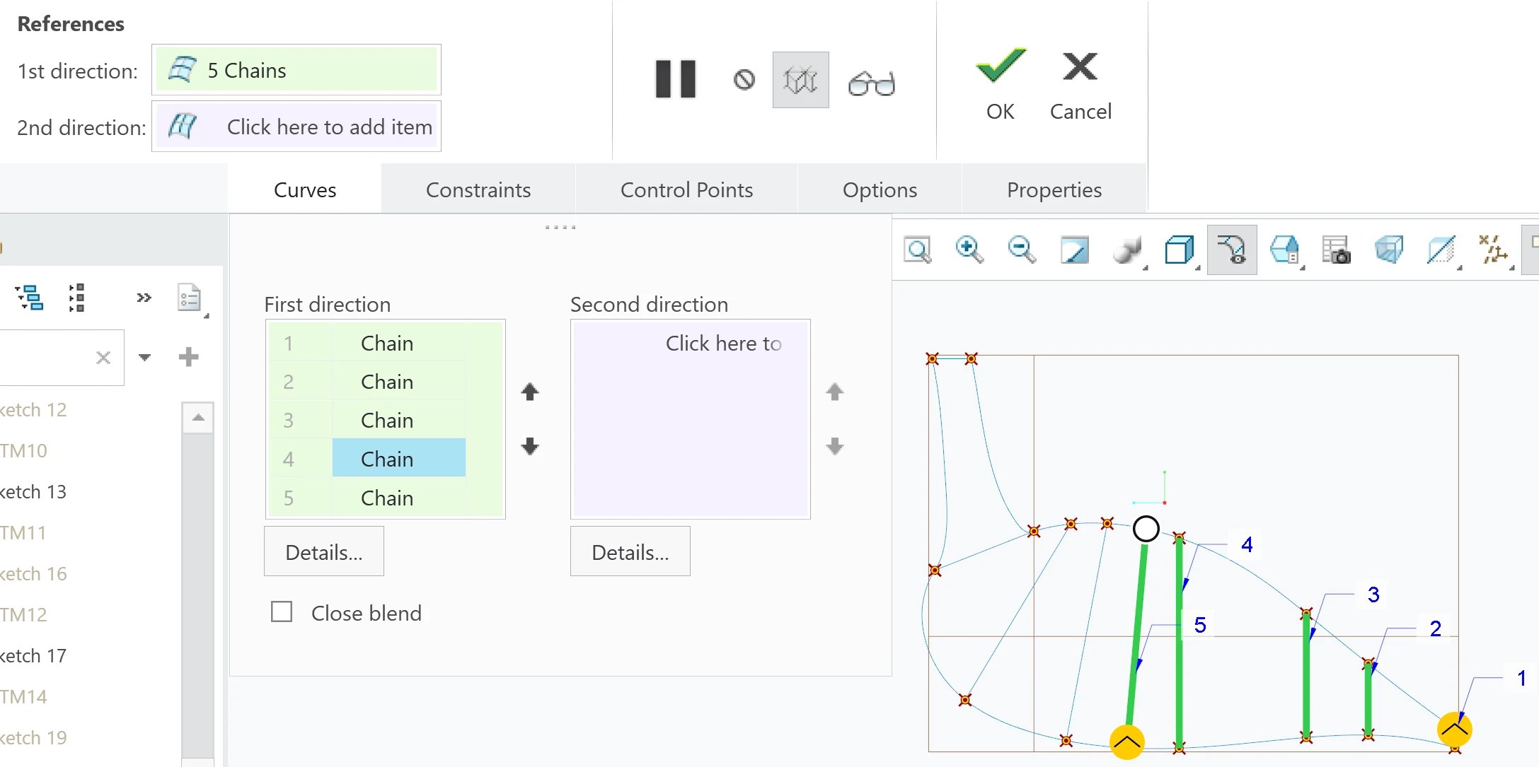
 Hello, I’m working on modeling a bird by using Boundary Blend. For some reason, it doesn’t work for the middle part of the body, but it works fine everywhere else. 


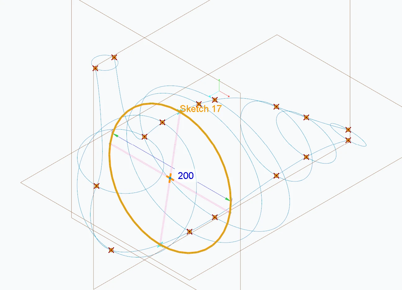
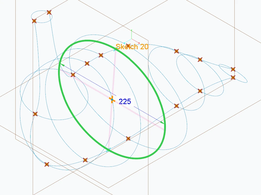
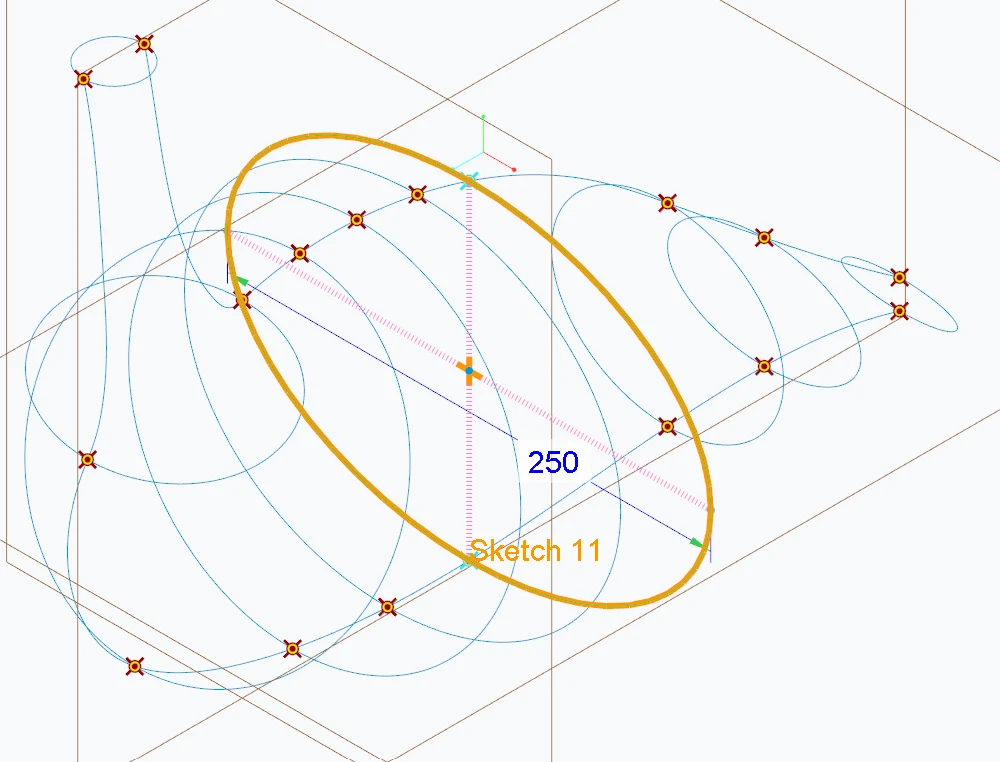
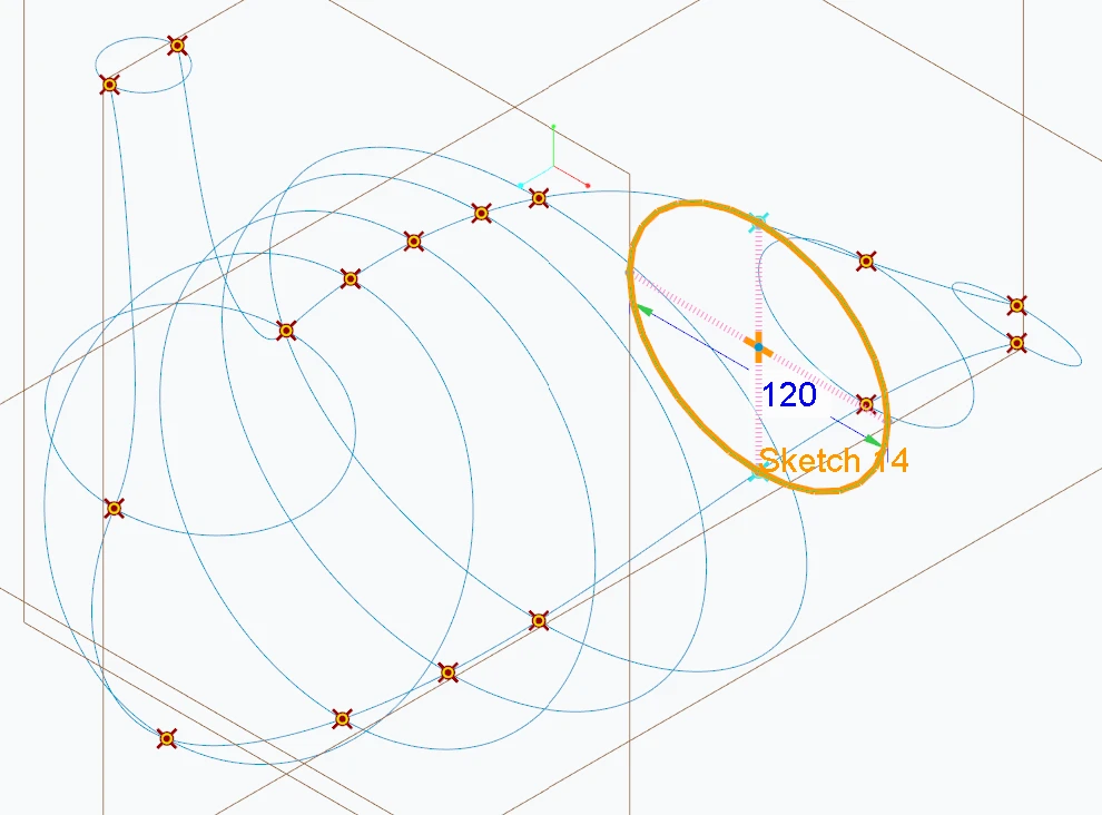
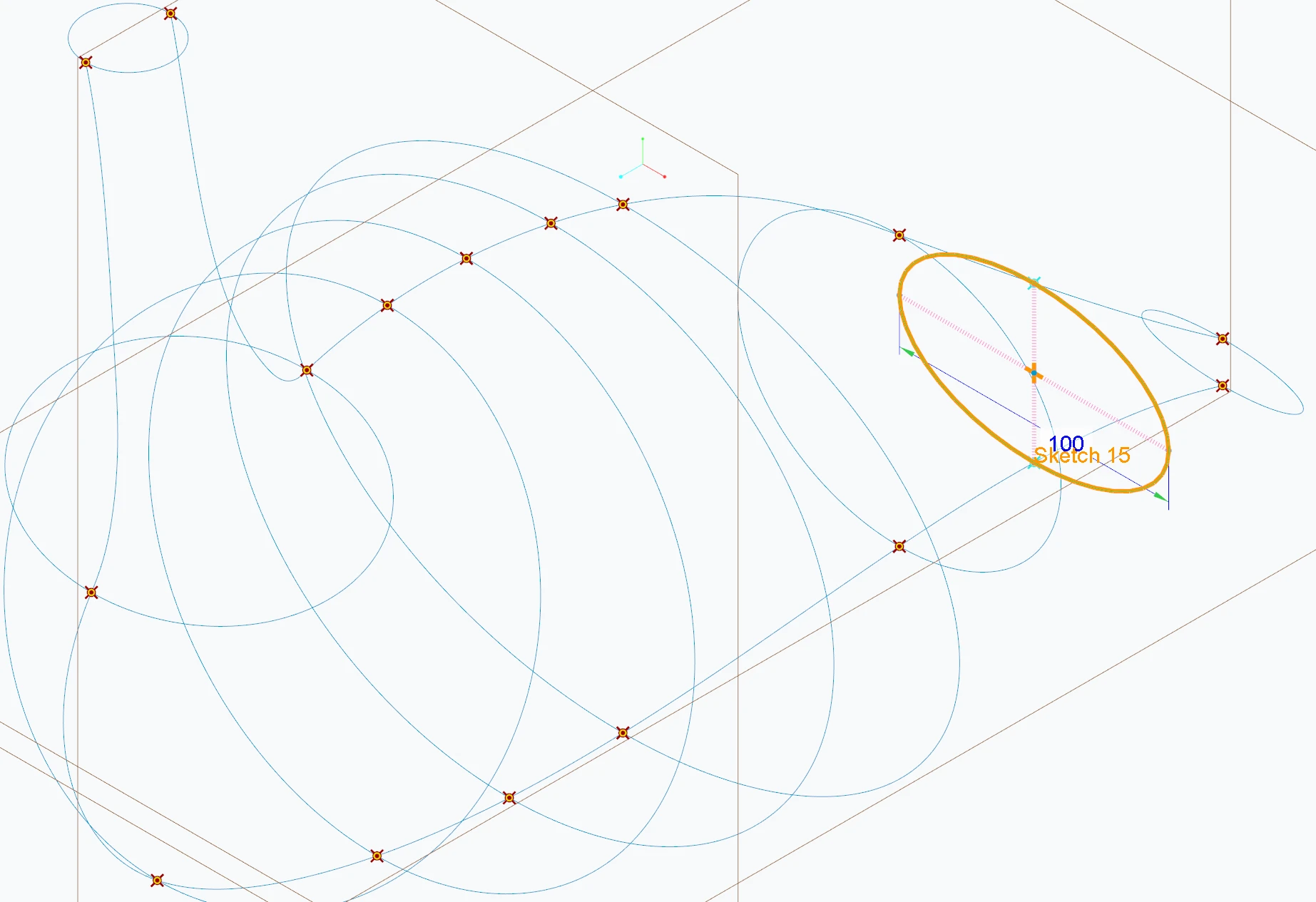
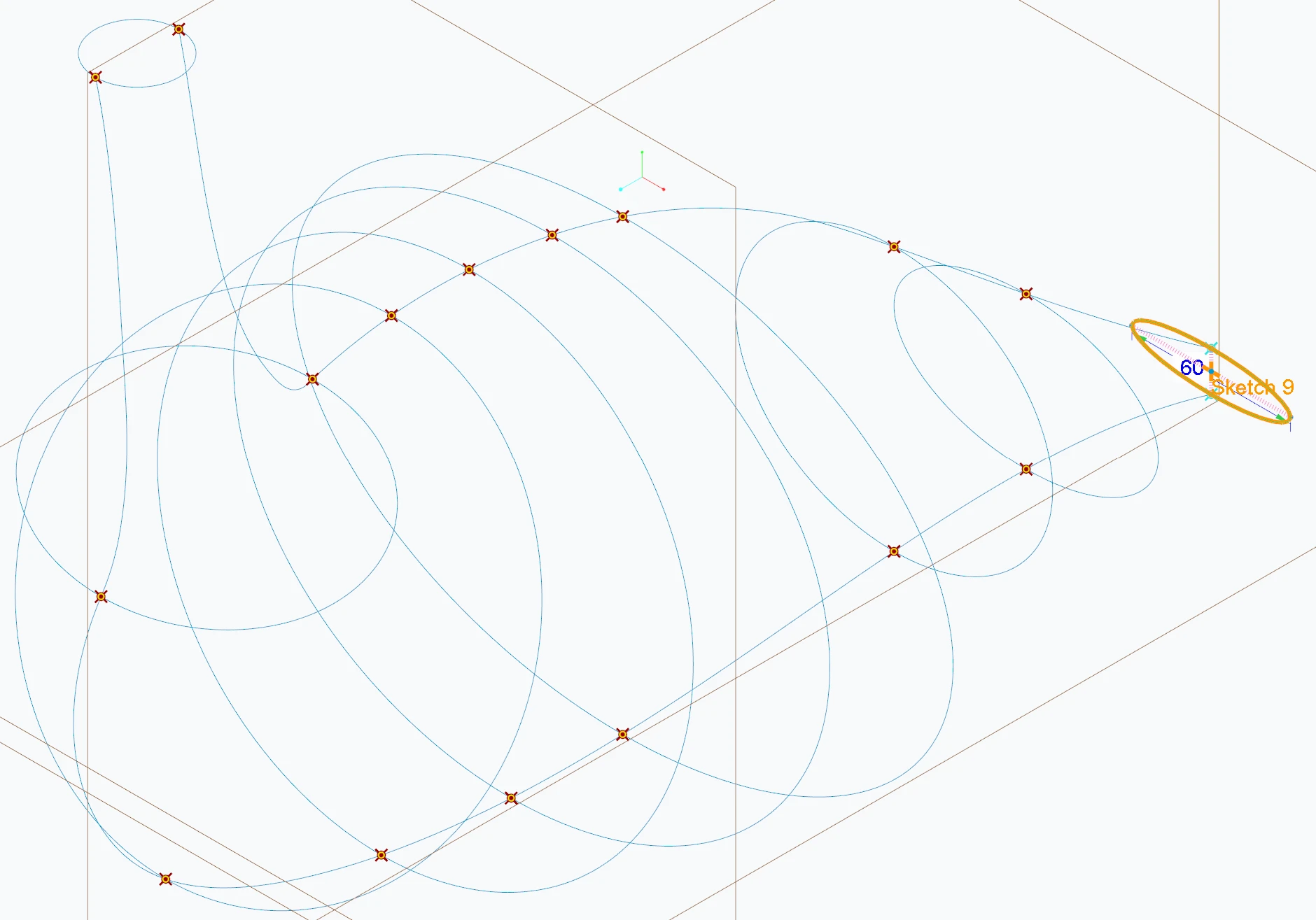
I made a bunch of datum points, axes, and planes. Currently, the four rightmost planes on which the ellipses are sketched are parallel to each other, the rest are not.
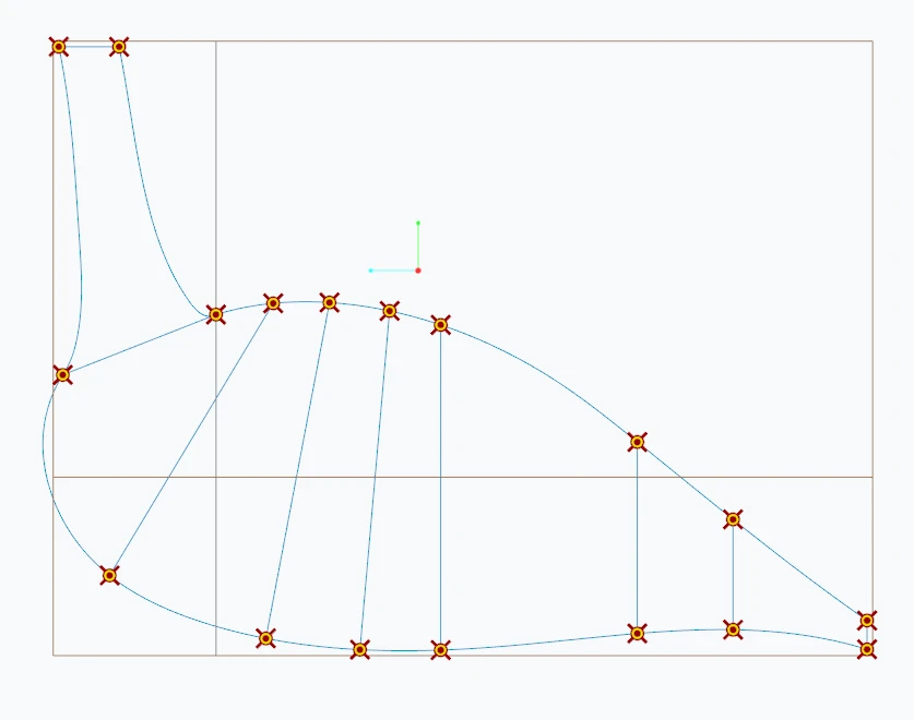
 

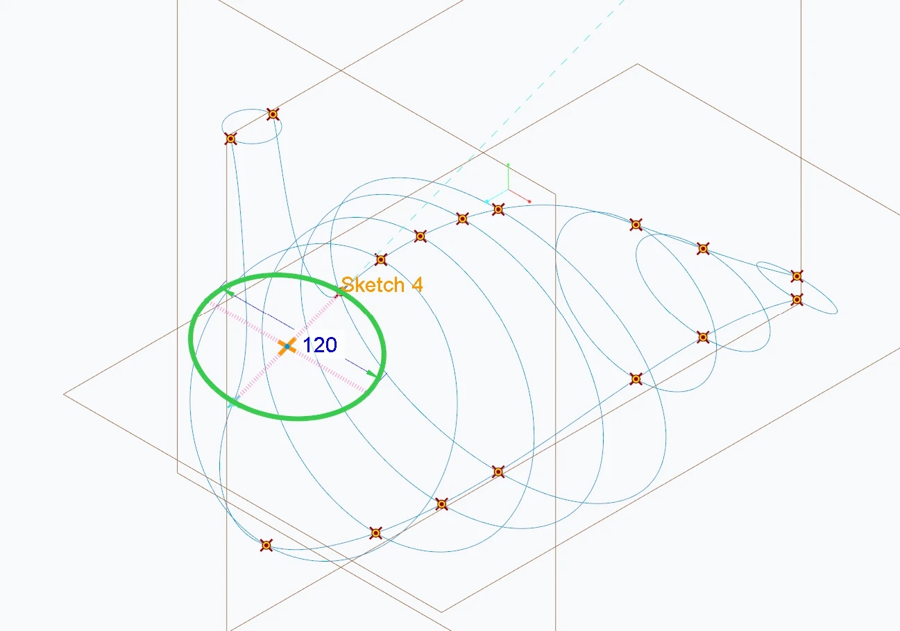
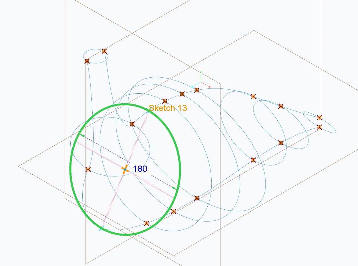
 Dimensions: (the first pair of ellipses coincide with the path of the body, so dimensions are for the second pair)
 

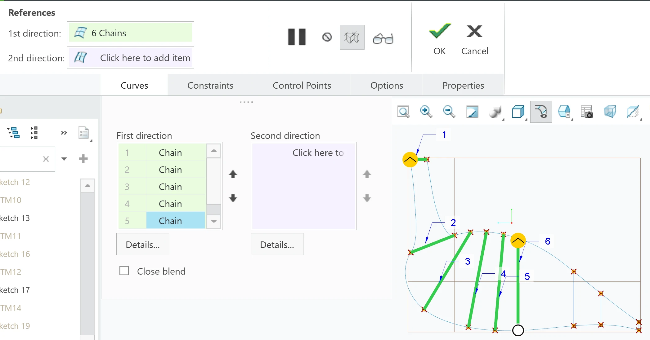
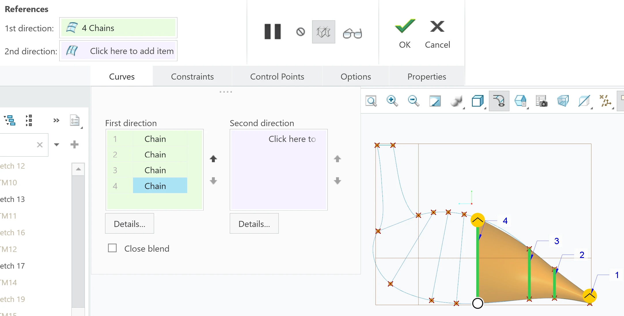
When I try to apply Boundary Blend, this is what happens:
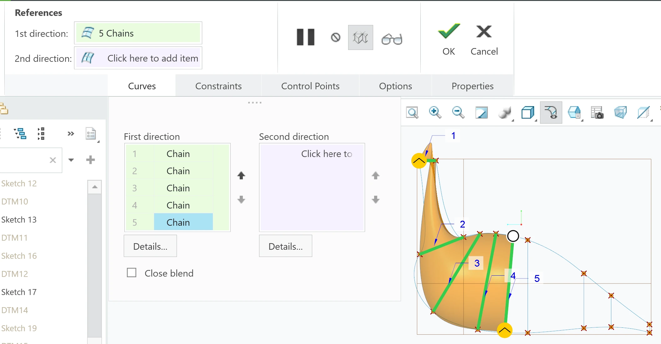
For some reason, Boundary Blend does not work between the 225 and 250 ellipses, but it works between the others. I’ve tried:

  • resizing either of the ellipses
  • adding more ellipses (180 and 225 ellipses were not there)
  • changing the distance between the ellipses (closer to each other, farther from each other)
  • changing the angle of datum plane for the 250 ellipse (it was vertical, it was parallel to 225, its angle from x-axis was smaller than the angle for 225, its angle was larger than the angle for 225)

I can’t figure out what the problem is. I don’t know what else to try. Please help as soon as possible. 

After the Boundary Blend, I plan to Solidify, then Shell.

    6 replies

    tbraxton
    22-Sapphire II
    Nov 14, 2026 6:14 PM UTC

    I want to commend your post as it includes good context and details about what you want to accomplish. Without seeing the nature of the failure, it is difficult to guess at what is wrong. If possible, post the part model here so that others can interrogate it. If you are not able to post the model, then show a screen shot of the failed feature and the error messages.

    Try breaking down the boundary blends to only use two sections(ellipse) as curves in the first direction and use the “spine” and “belly” curves as curves in the second direction.

    If I had to guess I would say it was an issue with control points. We need to see the “problem” to figure that out. Does the feature preview that is failing look twisted? Are you applying constraints to any of the boundaries of the blends? If you are blending between ellipses then the control points must be mapped appropriately.


    A tip: If your model is symmetric about a mirror plane (it appears that this is the intent) then model half of it and mirror it. It can speed things up and make managing changes less burdensome.

    Translate
    4-Participant
    Nov 14, 2026 6:52 PM UTC

    First, thank you so much for replying. It genuinely means a lot that someone is trying to help. Unfortunately, I can’t seem to post the .prt file. I wish I could. 


    I thought the last few pictures showed what the error is. I would assume that with Boundary Blend, when you pick the first and second directions, as you pick each sketch in a chain, the Boundary Blend would continue to develop (the orange surface). When something is wrong, the Boundary Blend stops developing and there is no more orange surface. Of course, I tried to complete all the Boundary Blend “jobs” I did including control points. However, whichever way I started when choosing the first direction, whether from the neck or the tail, the Boundary Blend stops developing between the 225 and 250 ellipses.


    The control points I used are the datum points that I made by intersecting the two paths with the ellipses that I sketched from datum planes. I made sure that each set of control points were for each path, I went from the neck to the tail. I didn’t put any constraints. 


    This is the error shown: 


    I don’t even know what the is causing the error. Creo isn’t telling me anything. The model looks the exact same as before I made the Boundary Blend. It’s completely empty except for the sketches I made. I’m just thinking it’s because of the 225 and 250 ellipses because of what I said above. 


    Translate
    tbraxton
    22-Sapphire II
    Nov 14, 2026 6:57 PM UTC

    If you place the part file inside a zip archive before uploading it should work. Are you using an educational license? If so, I will not be able to open the file but would be able to get it converted next week so I can open it.  If you can save your model with only the curves, no boundary blends as a Creo neutral file (.neu) and upload it here that will be helpful for troubleshooting. 

    Translate
    4-Participant
    Nov 14, 2026 7:14 PM UTC

    Yes, thank you, it worked. Attached is the zip file.

    I’m using an educational license, specifically Creo Parametric 13.4.0.0

    Again, thank you so much for helping me out.

    Translate
    4-Participant
    Nov 14, 2026 7:18 PM UTC

    Oh I forgot to say that after I made my initial post, I added a curve connecting the two paths at the tail, so in Boundary Blend, the second direction is just one chain. I was hoping it would do something, but nope :,)


    Translate
    tbraxton
    22-Sapphire II
    Nov 14, 2026 7:52 PM UTC

    I was able to use the curves from the neutral file to construct some boundary blends as indicated by the different colors. This was using your ellipse construction only. Each color is a boundary blend feature. If you attempt to use the belly and spine curves, then that is one of the problems as it introduces degenerate geometry and discontinuities. If your objective is to use boundary blends for this exercise, then focus on 4-sided boundary blends (2 curves in 1st dir & 2 Curves in 2nd direction).

    If you want a smooth transition along the body surfaces you need to refine your underlying construction curves. Think about breaking the constructs down into a series of 4-sided boundary blends with boundary conditions normal to the mirror plane (DTM RIGHT) and G1 or G2 across the mating boundaries of the boundary blend features.


    Model tree using blends from ellipse sections
    Spine and belly planar curve continuity issues


    Translate