

Cosmetic Thread Missing in Isometric Drawing View – Creo 9 / Intelligent Fastener
Hello everyone,
I have encountered an issue with the display of a screw in an assembly drawing created in Creo 9, and I would appreciate any help or suggestions.
I created an assembly consisting of two components. One of the components contains an M6x1 threaded hole, created using the Hole feature. I then used the Intelligent Fastener feature to place the corresponding M6x1 screw into this hole.
When creating a drawing from the assembly, I noticed an issue with the screw's cosmetic thread representation in the 3D (isometric) view.
Specifically, after the screw enters the mating component, the outer cylindrical surface of the threaded portion (Ø6 mm) is no longer displayed. The cosmetic thread line representing the minor diameter is still visible, but the line representing the major diameter (Ø6 mm) disappears.
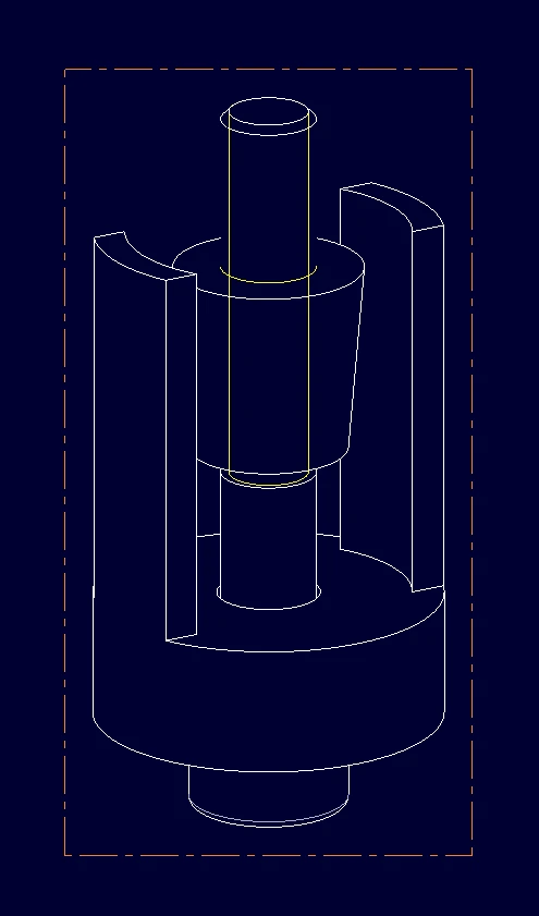
Interestingly, this issue only occurs in the 3D/isometric drawing view. In standard orthographic views (front, side, and top), the thread representation is displayed correctly.
If I change the view display style to Hidden Line, the missing outer diameter line becomes visible. However, I would prefer to keep the No Hidden display style.
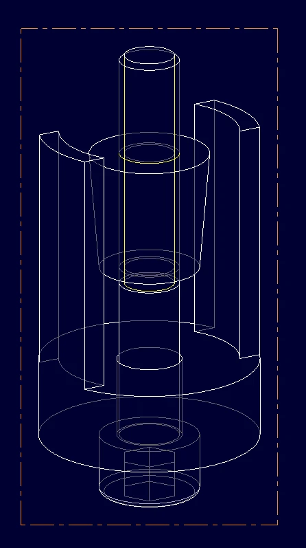
I have also tried the Erase/Unerase Cosmetics commands, but this does not solve the issue.
After looking through the PTC Community discussions, I suspect that the problem might be related to geometric overlap or interference between the screw's cosmetic thread representation and the mating component.
The threaded hole was created using the Hole feature, which represents the actual tap drill diameter (the minor diameter of the thread), rather than the nominal thread diameter of 6 mm. Therefore, the screw's nominal outer diameter (Ø6 mm) and the modeled hole diameter are naturally different.
I also tried an alternative approach: instead of using the Hole feature, I created the Ø5 mm tap drill hole using an Extrude Cut feature and then added a Cosmetic Thread feature separately. Unfortunately, this did not resolve the issue either.
It is important for me to maintain the correct technical drawing representation according to engineering drawing standards. Therefore, increasing the modeled hole diameter to match the screw's nominal outer diameter is not an acceptable solution for me, as this would result in an incorrect representation of the actual geometry and manufacturing requirements.
Is there a way to display the complete cosmetic thread representation correctly in a 3D drawing view using the No Hidden display style, without changing the actual hole geometry?
I would prefer to maintain the correct physical geometry of both components while achieving the correct ISO thread representation in the drawing.
Thank you in advance for your help!
Martin
EDIT: Sorry, I made a typo in my original post: the assembly actually consists of three components, not two. However, only two of them are relevant to the issue described.