

Creo Sheetmetal Unbend Feature Failure
Hi,
We are trying to unroll tubes from a chassis created in the AFX extension in order to produce templates for tube notching. The way we do this is by opening up the part for the tube and operations>Resume all to unsupress the flat pattern ID. This works for some of our tubes but fails for others. Does anyone know why this occurs? For example:
1) Rolled
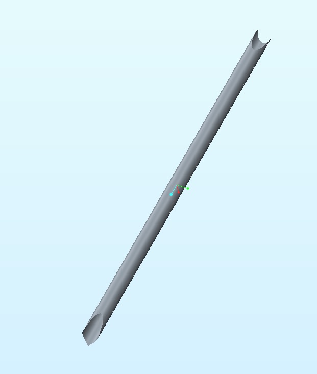
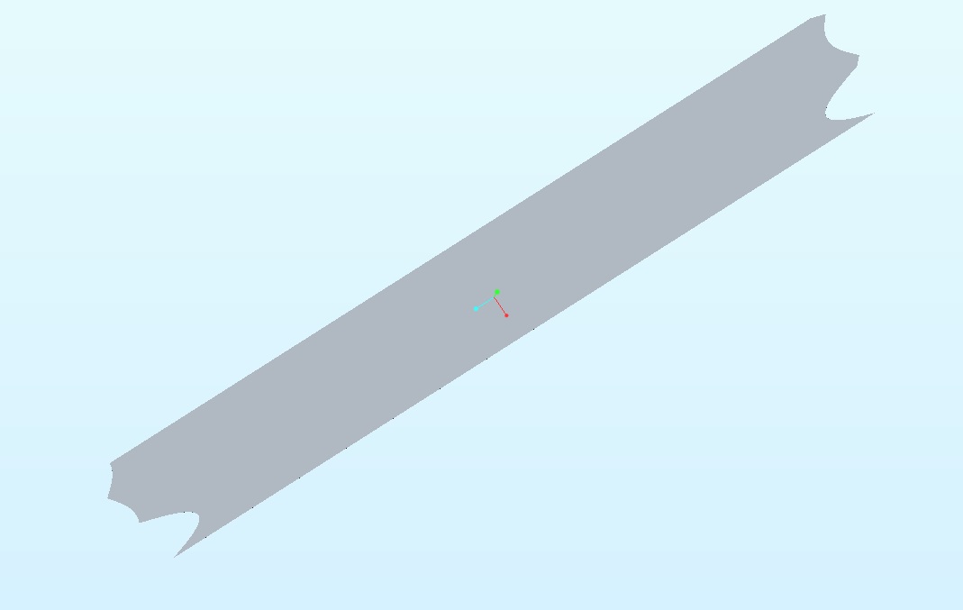
2) Unrolled
This works for the tube above but fails for the tube below. Flat does not regenerate when unsupressed.
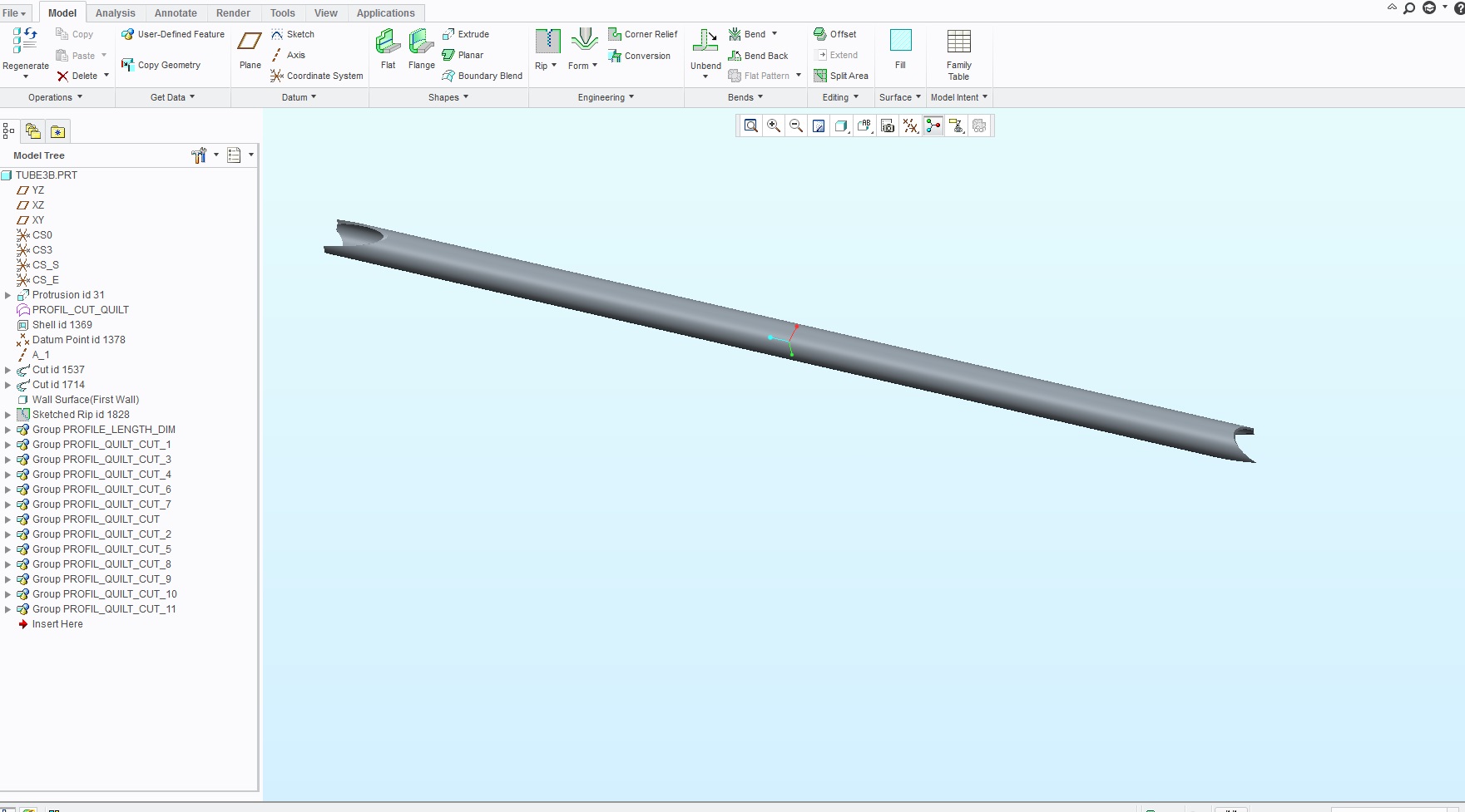
1) rolled
2) Failure to unroll
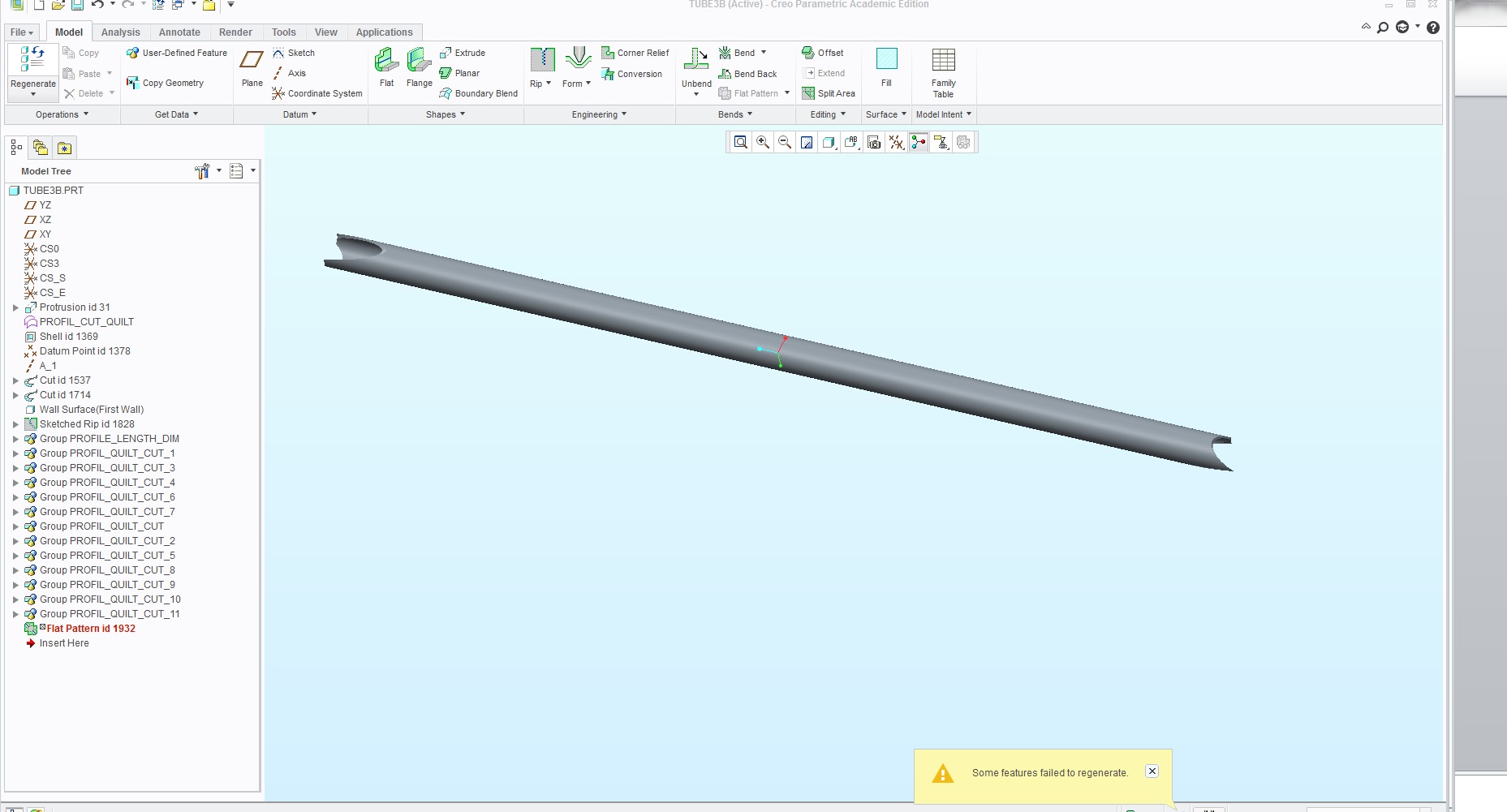
So the question stands What would allow one tube to display the flat when unsupressed but cause the flat to fail when unsupressed for another. Both of the tubes have multiple profile cutouts in each end. Looking to resolve this as soon as possible.
Thank You
Hafeez
This thread is inactive and closed by the PTC Community Management Team. If you would like to provide a reply and re-open this thread, please notify the moderator and reference the thread. You may also use "Start a topic" button to ask a new question. Please be sure to include what version of the PTC product you are using so another community member knowledgeable about your version may be able to assist.