1-Visitor
June 4, 2021
Solved

External parameters in assembly

  • June 4, 2021
  • 12 replies
  • 4779 views

Hi all
is it possible to link parameters to a notebook or excel in assemblies?
For example i would like to control the angles in this system of linkages (see picture) by changing values in a table.
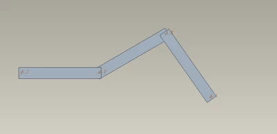

CreoCarlos_0-1622796483748.png


Best answer by tbraxton

Yes, layouts can be declared to assemblies and skeleton models. The main function of Notebooks is to define global parameters and then propagate them in a top down design. The example I posted above is used to drive multiple internal combustion engine architectures that employ skeletons, assemblies, and mechanism definitions.


With the notebook in session, open a part or assembly.
For a part, click Model Intent ▶ Image Declare. For a part or an assembly, click File ▶ Manage File ▶ Image Declare. The DECLARE menu appears.
Click Declare Nbk. A menu with a list of notebooks active in the current session appears.
Select the name of the notebook to which you want to declare the model. The model now references the notebook


12 replies

1-Visitor
June 4, 2021

i am using creo 4.0 commercial license 

16-Pearl
June 4, 2021

Hi CreoCarlos,


You could try from excel from here:

ANSWER.png

1-Visitor
June 7, 2021

Turns out excel analysis is quite a good tool for a lot of stuff, thank you !

tbraxton
22-Sapphire II
June 4, 2021

You can use a Creo Notebook (.lay) file to manage the definition and propagation of parameters to models. You can declare and undeclare the layout to a given model to enable or disable the functionality. Tables are supported in Notebook files.


This is an example of a Notebook used to control multiple parts and assemblies from a table.


Notebook with a tableNotebook with a table

1-Visitor
June 7, 2021

Yes but this only works for components doesn´t it?

I can´t declare a notebook to an assembly and thus i can´t control its positoning nor is it possible to declare it to a motion skeleton.

12-Amethyst
June 4, 2021

You can also create a drawing in Creo, build a table and add the parameters into the table to control the angles.

1-Visitor
June 7, 2021

Does this work with assemblies aswell? I know it works to control components but can you control positions in assemblies?

16-Pearl
June 7, 2021

Hi CreoCarlos,


With excel it works fine, with these 2 cells I control angles:


1.png

I changed the values, and regenerated the assembly:


2.png
