
14-Alexandrite
August 17, 2023
Solved

Good practice in extruding to surface

  • August 17, 2023
  • 2 replies
  • 3904 views

Hello,
I am trying to recreate this model from solidworks model mania 2006 which consists of two phases, changing your model from 
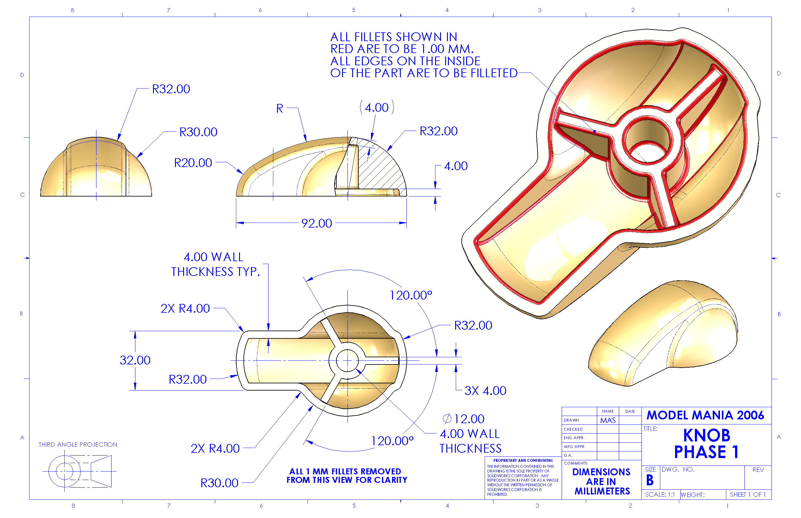
to the one below.

Basically adding a taper and a draft. While doing this I realised my initial sketch that was extruded to the surface was not enough to handle the taper.

The surface(created using a sweep) and my initial sketch below ( the sketch is a bottom up projection of the surface edges.
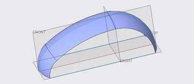
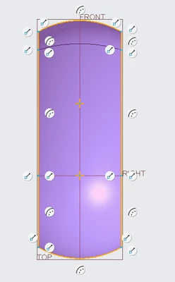
IbrahimTayyab_0-1692277082702.png

IbrahimTayyab_1-1692277118356.png

When extruding without a taper it works perfectly. 
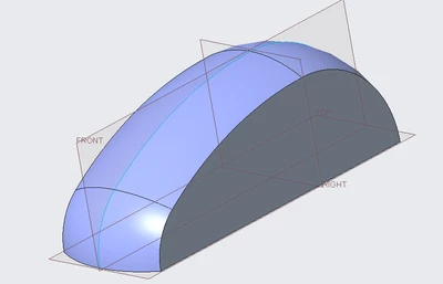
IbrahimTayyab_2-1692277208815.png

However when I add a taper of 15 degrees to it, the extrusion no longer fits to the surface as nicely as before.
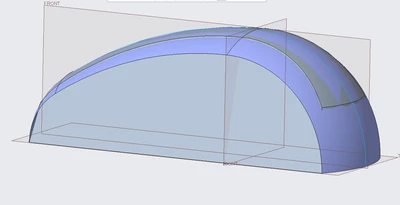
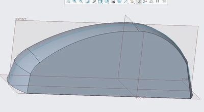
IbrahimTayyab_3-1692277288952.pngIbrahimTayyab_4-1692277301957.png


The fix I found for this was modifying my sketch to be taller than the projected area.
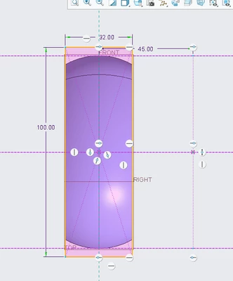
IbrahimTayyab_5-1692277447783.png

This resulted in an extrusion that fit much better to the surface.
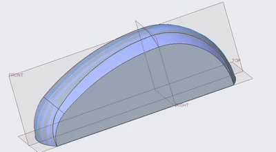
IbrahimTayyab_6-1692277492515.png

I am sure I am probably messing something so I would really any tips on why the projected area extrusion doesn't work.


I am using creo parametric 9.0 student version

Best answer by kdirth

I think your modification should be adding a draft feature rather than adding taper to the extrude.

Here is how I would create it (some of this may be what you have done):

  • revolve the half sphere
  • sketch the center profile and sweep a surface
  • extrude upto the surface
  • shell model
  • create ribs
  • add rounds

Modifications:

  • move insert above shell
  • draft the side of center
  • move insert to end
  • add taper to ribs
  • fix rounds if needed.

2 replies

kdirth
21-Topaz I
kdirth21-Topaz IAnswer
21-Topaz I
August 17, 2023

I think your modification should be adding a draft feature rather than adding taper to the extrude.

Here is how I would create it (some of this may be what you have done):

  • revolve the half sphere
  • sketch the center profile and sweep a surface
  • extrude upto the surface
  • shell model
  • create ribs
  • add rounds

Modifications:

  • move insert above shell
  • draft the side of center
  • move insert to end
  • add taper to ribs
  • fix rounds if needed.
There is always more to learn.
kdirth
21-Topaz I
21-Topaz I
August 17, 2023

Here are screen shots of both versions with model tree.

kdirth_0-1692282325594.png

kdirth_1-1692282483397.png


There is always more to learn.
tbraxton
22-Sapphire II
22-Sapphire II
August 17, 2023

It appears that you are following some tutorials, but they often lack context on how the tools are best employed in industry. I will offer some context based on experience with designing parts that are made using a mold.


When designing parts such as this that will require draft for tooling reasons and has wall thickness requirements it is often advantageous to use surface features to get the shelled form. This can provide much more flexibility during the design process for these types of parts. This specific part can easily be built as solid features, but I would encourage you to rebuild it using surfaces as an alternate exercise. If you develop proficiency with surface modeling, you will be much more effective and efficient when designing using Creo Parametric. Compare both approaches to creating this geometry in the context of building design flexibility and regeneration robustness into the model.


The video below demonstrates how surface modeling could be used to generate the shell geometry. This is not the only way to do it.

14-Alexandrite
August 17, 2023

Initially I attempted to create it using surface modelling but I failed miserably however your video guide has given me a lot of insight especially on the functionality of the merge tool. Thank you very much for taking the time out to show this.


As a side note I saw that you created the side wall of the model using a sweep (Sweep 2) instead of for example something like a rectangular fill. I understand you have mentioned this is not the only method in creating this geometry but I feel you must have an interesting reason behind this. I also do not completely understand its geometry either, could you kindly elaborate on it?

tbraxton
22-Sapphire II
22-Sapphire II
August 17, 2023

I used a sweep as it is a single feature to generate a planar surface that extends beyond the quilts, I want to merge it with. The dimensions I show in the video are extensions of the sweep origin trajectory on both the proximal and distal ends to ensure the surface extends beyond the quilts it will be merged with.