5-Regular Member
July 23, 2026
Question

Harness Assembly repeat region pin not working

  • July 23, 2026
  • 6 replies
  • 103 views

Hello! I’m trying to make a simple cable harness 2 wires going from connector 1 to connector 2.

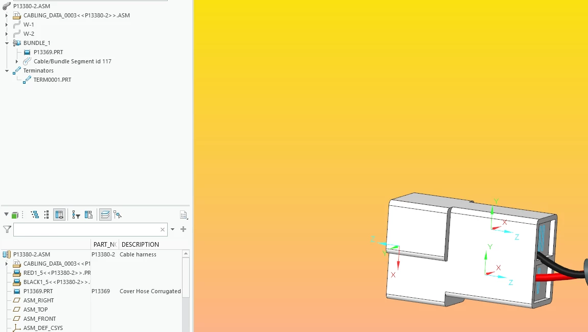
There are 2 coordinate systems in each connector that I have made.

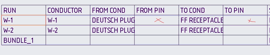
On my drawing i’m trying to use repeat regions to display which port in the connector each wire should connect to. However no pin no. gets displayed, it doesn’t matter if I select the repeat region to be driven by the assembly or the connector part.

I’m using &harn.run.cond.from.pin.entry_port and have tried a bunch of others but it remains blank regardless.
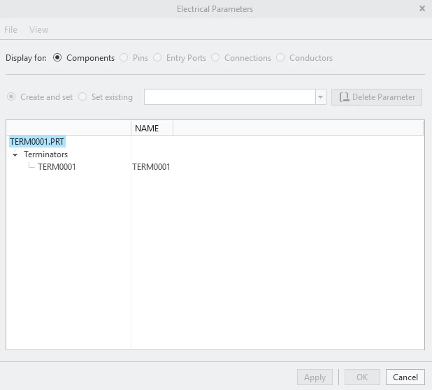
I have tried creating Terminators inside the assembly but am unable to do anything besides create it? No editing or anything seems to be possible. I read some other posts where they supposedly add cabling parameters somehow? I don’t see how to do it.
Any help to display pins on the drawing would be greatly appreciated!

6 replies

Mahesh_Sharma
22-Sapphire I
July 23, 2026

Hi ​@AS_10987481 


Flat harness file needs to be selected for the reported Connector Pin table details; not the harness manufacturing assembly. I hope you are using flat harness assembly to create a repeat region table.


Thanks. 

5-Regular Member
July 24, 2026

Hello Mahesh,

What is this flat harness file you mention? Do you mean the cabling data file?


I tried using the harness mfg application but it autogenerates tabls without any relations so I can’t really work with that effectively. Current result of that looks like this:


Best Regards, Alex

14-Alexandrite
August 3, 2026

Hi,

It seems that you are using the newer Creo versions since your terminators are parts? And is the cable the P13369.PRT?

We are still using the older Creo and on older Creo you need to use the harness part as the selected model for the table to show the from-to pin numbers.

So in your case I would try to select the Cabling_data_003____.asm as the model for the table.
On older Creo the "From-pin" parameter was the 
&harn.run.cond.from.pin.name

and the "to-pin" parameter was
&harn.run.cond.to.pin.name.


There was also no need to do the flat harness files to see the pin numbers. The cable part file has all the connection info that can be used on the table. If you need the flat representation then you select the File->New->Manufacturing->Harness (if it still exists). We don't use the Harness Mfg button since it is a separate license that costs money. You can achieve similar results with the Manufacturing-harness option, although it is harder to use.


Old Creo also allowed editing terminators via the "Logical Data -> Terminators -> Edit"
We usually had the parameters "Description", "Manufacturer", "Catalog" on our terminators. Since the new terminator is a part then perhaps you can just edit the part parameters and add whatever info you need for the part.

I am looking forward to our upgrade to the newer Creo version. The expectation is that, in the future, we will be able to create complete harness BOMs in Windchill, since cables, wires, and terminators can now be managed as parts.


Br, Lars

5-Regular Member
August 3, 2026

Hello!

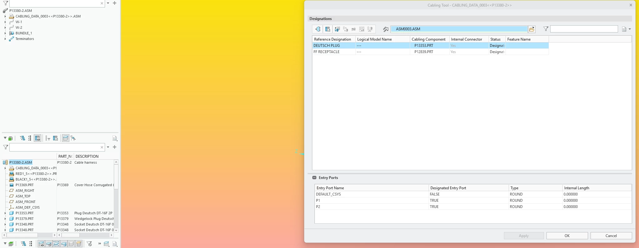
Yes I’m using Creo 12 and harness assembly to make my cable harness. I found the repeat region reference names but the problem I had was there were no pins designated for my connectors. I did however manage to find how to designate them now manually:

Then

By adding the columns. I hadn’t figured out how to add these to the electrical parameter columns earlier. Now I just need to figure out how to make the program automatically detect coordinate systems in my connectors so that they get auto assigned to pin numbers. Also I will try the “manual” harness manufacturing method for flat drawings. About the terminator I thought it might be used for pins assignment but I was mistaken.


Best Regards

14-Alexandrite
August 4, 2026

Hi,

In Creo, Terminators define how a conductor is terminated at a connector. Each connector pin can have its own TERM_NAME parameter:
<PARAMETER name="TERM_NAME" value="60413-1" />

We primarily use terminators to specify which crimp terminal the subcontractor should use for each connector pin. Different pins within the same connector can use different crimp terminals. For example, if some pins use thicker wires than others, they may require a different crimp part.

The preferred way to create Creo cables and harnesses is to start from a logical harness definition rather than routing everything manually. The most common approach is to create the harness logic in Creo Schematics and then import it into Creo Cabling.

Another option is to generate a neutral wire list (.nwf) file from Excel using a custom macro and then import that into Creo. There are examples discussed in the PTC Community: https://community.ptc.com/3d-part-assembly-design-327/nwf-file-34196

If you're a bit more adventurous, you can also use KiCad together with the kicadToCreo converter to generate Creo-compatible harness logic directly from schematics.

AI's suggestion...
In larger organizations, the most common harness workflow is typically:
Capital / E3.series / Arcadia / EPLAN → export harness logic → import into Creo Cabling → perform 3D routing → generate manufacturing documentation using Harness Manufacturing Extension (HMX).
 

Br, Lars

5-Regular Member
August 5, 2026

Hey, thanks for the answers!

Yeah at my org. we haven't used creo for harnesses before, everything has been done in separate software like RapidHarness. I might have to try using creo schematics to create the harness logic as you said, it does seem to be the preferred way to work & maybe that’s why it hasnt been smooth sailing yet!


B.R. Alex