
Solved

I have to reitterate this comment. I mis-understood the R313 and R17 callouts. This is a fairly straight forward extrude but it is missing the draft requirement.
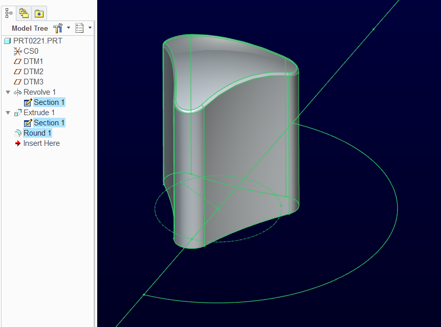
I created a R170 hemisphere and extruded the triangular shape with the remove "remove material" and flipped the removed material to the outside.
I don't know what the triangular shape is from the limited details provided.
Enter your E-mail address. We'll send you an e-mail with instructions to reset your password.