1-Visitor
March 20, 2013
Solved

How can I create a 3D dimension for diameters?

  • March 20, 2013
  • 1 reply
  • 4174 views

Hello,

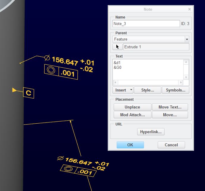
I have been trying to create a 3D dimension for circular/cylindrical features. Im actually using Creo Elements Pro 5.0. I'm using this feature.

Insert > Annotations > Dimension

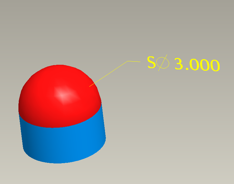
I need to create the dimension on a pin once it has been assembled, so I can attach a datum to the dimension. Creating the dimension on an spherical features works pretty well but I didnt have any luck with cylinders. In the image below it is shown how I put the dimension on the red surface (the sphere) but I can't do the same for the blue one (the cylinder).

Capture.PNG


This thread is inactive and closed by the PTC Community Management Team. If you would like to provide a reply and re-open this thread, please notify the moderator and reference the thread. You may also use "Start a topic" button to ask a new question. Please be sure to include what version of the PTC product you are using so another community member knowledgeable about your version may be able to assist.
Best answer by TomD.inPDX

You can manipulate quite a bit of this. Datums can be assigned to several features; the diameter dimension can be shown as linear; the GTOL is a feature much like a dimension and can be added to a note feature. Orientation can also be edited.

I am certain you will run into limitations but maintaining associativity shouldn't be difficult.

dim_note_2.JPG

Taking the dimensions to another level through an assembly should also be possible. You will have to find the feature in the sub-level and find the value as used in assemblies.

1 reply

17-Peridot
March 20, 2013

You can make a note annotation attached to the surface that used the dimension from the cylinder's diameter dimension.

dim_note.JPG

1-Visitor
March 20, 2013

I mean, if there is a way to do it with the feature I mentioned, Insert>Annotation>Dimension. I need to create the dimensions on the assembly, that way I can add datums and geometric tolerances to the assembly and show them on the drawing. Maybe my whole way is wrong, but at least it has worked for other things. I design with tooling balls so adding datums to the sphere is ok, but the problem is when I need to add datums to a dowel.

17-Peridot
March 20, 2013

I see. Typically, you can only do what ASME Y14.49 will allow you to do. In the case of the cylinder, it is typically the dimension shown on the bottom. You can change the arrows-out but that is normally it.

However, that dimension, &d1, does have all the intelligence of the original. Have you tried formatting the dimension and then adding it to a note feature?