13-Aquamarine
March 31, 2023
Solved

How can I create a helically swept S shaped flute?

  • March 31, 2023
  • 10 replies
  • 3699 views

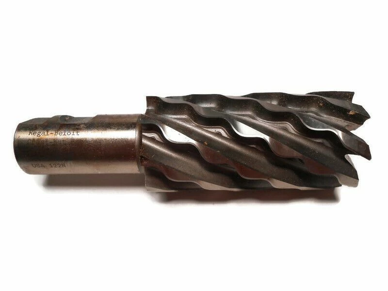
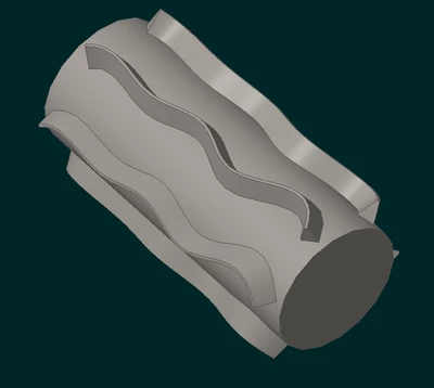
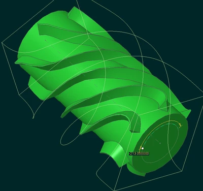
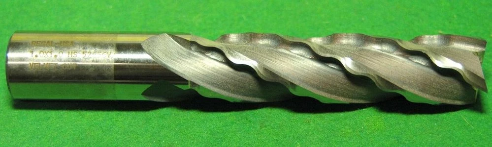
I am trying to recreate a velvet endmill, and frankly, I have no clue where to start with modeling this.  Usually, I use a helical sweep to model normal endmills, but this has me stumped.


s-l1600.jpgs-l1600.jpg 


Best answer by pausob

Interesting, never seen one of these.

Off the top of my head, the variable section sweep using of trajpar equation involving (co)sine is the go-to for these kinds of "periodic" features.

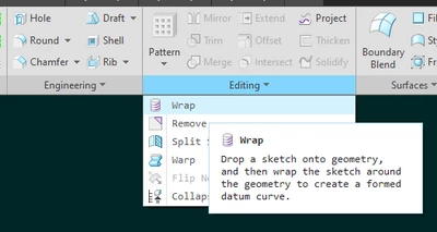
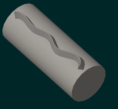
But maybe the "wrap" tool could be used to get the snaking curve to follow the helical path around your stock cylinder? 

pausob_1-1680268414703.png


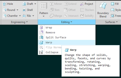
The other way would be to make a "straight" protrusion (with undulating sides), pattern, then twist using the "warp" feature:

pausob_2-1680268645428.png


pausob_3-1680269483285.pngpausob_4-1680269496033.png


pausob_5-1680269528363.png


10 replies

pausob19-TanzaniteAnswer
19-Tanzanite
March 31, 2023

Interesting, never seen one of these.

Off the top of my head, the variable section sweep using of trajpar equation involving (co)sine is the go-to for these kinds of "periodic" features.

But maybe the "wrap" tool could be used to get the snaking curve to follow the helical path around your stock cylinder? 

pausob_1-1680268414703.png


The other way would be to make a "straight" protrusion (with undulating sides), pattern, then twist using the "warp" feature:

pausob_2-1680268645428.png


pausob_3-1680269483285.pngpausob_4-1680269496033.png


pausob_5-1680269528363.png


nlehman13-AquamarineAuthor
13-Aquamarine
March 31, 2023

tool.pngThanks, I did end up going with the warp since with my skill level in Creo, it's much easily achieved.  And it doesn't need to be accurate, this is just used for tool sheets, and material removal simulation that only needs the diam and length to be accurate.

Patriot_1776
22-Sapphire II
March 31, 2023

Ah.  That's why I mentioned whether you need it just for looks, or for accuracy, and that would determine methods needed.  Warp is excellent for things like this because it's actually very good at, well, "warping" geometry, in that it pretty much will not fail.  The downside is that you can't really control it, and you get what you get.  You can see that from the fact that at the distal end (from the chuck) that the twist is basically zero.  It's been a long time since I played with Warp (since I find it basically just a toy for my uses), but I think to correct that you can make that "bounding box" that's used to affect the geometry, be off the end of the part so that the twist actually affects even that end.  OR, make it longer than you need, and cut it off before the twisting stops.  I could be wrong, but I thought that was what I'd done years ago, the last time I played with it.


I guess what I'm surprised at the most is that they are finishing cutters.  I would have thought, from the similarity to the roughing cutter pic I posted, that they were a new roughing tool.  I've seen a lot of cutters in my time, but that's a new one on me.  Gonna have to look them up.


Glad you got what you needed here, and best of luck!

kdirth
21-Topaz I
March 31, 2023

I agree with creating a wrap.  Create a coordinate system rotated on the Z and a curve from equation to wrap around the cylinder.  Then sweep the curve.


kdirth_0-1680270681303.png

kdirth_1-1680270754467.png


There is always more to learn.
Patriot_1776
22-Sapphire II
March 31, 2023

Interesting, I've never seen an endmill like that.  I can see the advantages for it though in breaking up chips.  Is it used for things like stainless that are a PITA to machine and/or for high material removal rates?


As far as actually modeling it, do you want something that just LOOKS kinda like it, or do you need to actually model the geometry?  If it needs to be accurate, you're going to have to measure it and that will probably determine your methods.  From what I see, a simple wrap isn't going to be enough.

KenFarley
21-Topaz II
March 31, 2023

My guess would be that it cuts smoother because of chip break but maybe also because it will maintain more points of contact as it spins, so might be less apt to chatter? Maybe the type of contact it makes prevents harmonic vibration?

I can't imagine what a nightmare it would be to sharpen one of these. It must be done by very special equipment.

Patriot_1776
22-Sapphire II
March 31, 2023

'Sup Ken!


Yeah, I've seen a bunch of "roughing" milling cutters over the years, some with "teeth" instead (to break up long stringy chips that break tools and FUBAR the material being machined), so, maybe this is simply a variation on that.  This example below seems to have MUCH simpler geometry (to model and especially to manufacture/grind the edges).  So, to me, this looks like it's made to be used on stainless or other "gummy" metals and/or for fast material removal.

ROUGHING ENDMILL.png