1-Visitor
April 10, 2018
Solved

How to correctly add tolerance to manually added dimensions in Creo drawing?

  • April 10, 2018
  • 1 reply
  • 11364 views

Hi All, I would like to know how to correctly add tolerance to manually added dimensions in Creo Drawing? 

Take below picture for example, the two red dimensions were added on the Creo drawing by "Show Model Annotations" ,and Creo can show it's tolerance correctly according to the tolerance table I specified. The yellow dimension was added manually(means I added the yellow dimension by the button "Dimension"), the tolerance +/-0.02 is apparently wrong, anyone knows how to solve this issue? By the way, same tolerance set up were applied on both yellow and red dimensions, thanks. 
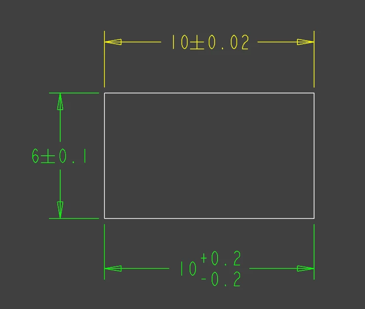
Creo tolerance.PNG


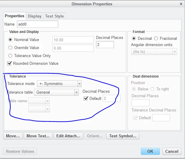
Tolerance set up

Tolerance setup.PNG

Best answer by MartinHanak

Hi,


  • model units are millimeters
  • drawing units are inches

If you change drawing units to millimeters then the problems disappears.


Note: Problem is related to addN dimensions. These dimensions are created only in case that config.pro option CREATE_DRAWING_DIMS_ONLY is set to YES.

1 reply

24-Ruby III
April 10, 2018

Hi,


  • tolerance standard is set to ISO in your drawing
  • tolerance class is set yo Medium in your drawing
  • dimension 10 is driven by Tolerance table General
  • General tolerance table is defined in general_def.ttl file
  • tolerance value is 0.2 ... see following picture


Please upload your drawing. I can check it.

general_def.ttl.png

zli-31-VisitorAuthor
1-Visitor
April 10, 2018

Attached is drawing, thanks.

24-Ruby III
April 10, 2018

Hi,


  • model units are millimeters
  • drawing units are inches

If you change drawing units to millimeters then the problems disappears.


Note: Problem is related to addN dimensions. These dimensions are created only in case that config.pro option CREATE_DRAWING_DIMS_ONLY is set to YES.