
1-Visitor
February 25, 2013
Solved

How to create a nozzle removing material with variable section sweep?
  • February 25, 2013
  • 5 replies
  • 14411 views

Slide1.JPG

Hi!

I need some help on below:

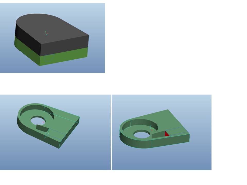
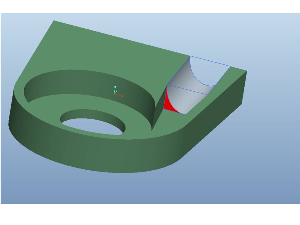
I am working on a plastic casing that has two main components as shown in the very first picture. There is already an inner cavity (turbine shaped cut to accept water) that ends to a rectangular opening. Client asked me to add material and extend this nozzle so that in the next 15cm to turn into a circle or ellipsis of same area.

In other words, we need to cut a almost tubular nozzle, which starts as rectangular and ends smoothly as circle or ellipsis.

Pls see in red above, the rectangular surface where removing material should start.
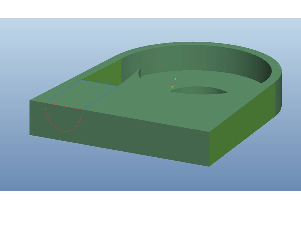
Slide2.JPG

Since the ELLIPTICAL OUTLET OF NOZZLE should be created by the assembly of the two parts, we need half of the cut at each part.

That is why I have sketched a curve on the surface that we be removed to have it a refererce.
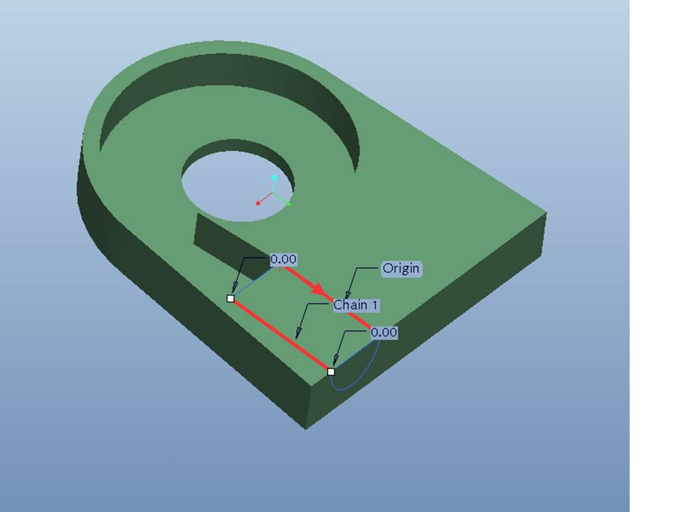
Slide3.JPG

I tried Variable Section Sweep , with two trajectories that lead from the rencangular to the hald-ellipsis shape and I sketched a half ellipsis section.

And I get this:
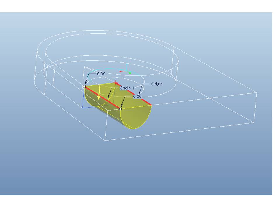
Slide4.JPG

which of course is not variable section cut, but only one section.
Slide5.JPG

This cannot give me a smooth trancation for rectangular to elliptical opening.

Any advise or amendment to my thought?

I am not very familiar with variable section sweeps but I think there might be an easy way that I just dont know.

Please help me , the soonest the better. I m in despair!

Thanks,

Amanda


This thread is inactive and closed by the PTC Community Management Team. If you would like to provide a reply and re-open this thread, please notify the moderator and reference the thread. You may also use "Start a topic" button to ask a new question. Please be sure to include what version of the PTC product you are using so another community member knowledgeable about your version may be able to assist.
Best answer by TomD.inPDX

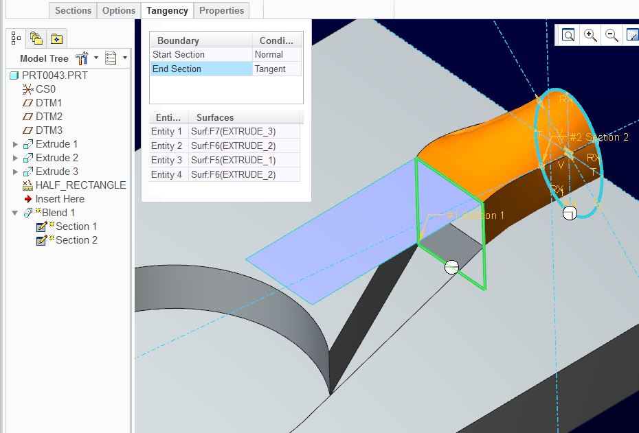
And just for completeness, I took this to the next level and added tangency to the tapered surfaces. Since I was using the "full" section, I needed a surface to define one of the tangencies (blue surface on top). Now the rectangular end is tangent to all 4 faces entering the rectangle and all the transitions are smooth.

rectangle-2-oval_iii.JPG

5 replies

17-Peridot
February 25, 2013

You just need the same number of segments in each sketch so you may need to break up the ellipse in the right locations. There is also no need to make only half the feature since it is a remove material feature.

I'll give it a try but that is the jest of it.

17-Peridot
February 25, 2013

Yep, that works. Simplified version:

rectangle-2-oval.JPG

The crossed centerlines are used to define the ellipse "break point" by using "Divide" in the editing group/

You can control the ellipse in one of many way. Just know that a divided ellipse becomes a handful to manage as they now require constrains for each segment.

You get the options to make the ends straight, smooth, or tangent, etc.

This should all work the same way with blend in your version.

1-Visitor
February 25, 2013

I am trying to understand what do you mean by dividing ellipse!

I have to draw also in sketch the crossed centerlines in order to get them as entities?

and what is the " divide " in "EDITING tree" ?! I need to go to the model tree and select any "divide" option?

I need a hint please!

13-Aquamarine
February 25, 2013

The easiest approach might be to use a variable round, starting very small to give a rectangle with slightly rounded corners and finishing very large to give a circle, or very close.

Otherwise I think you're looking for a Swept Blend; the trick to remember is that each section within it must have the same number of entities - so if you draw three sides of a rectangle in the first section, you need to break up your semi-circle into three sections in the last one.

Patriot_1776
22-Sapphire II
February 25, 2013

....unless you do a blend vertex....

1-Visitor
February 25, 2013

Is it an extra feature in swept blend? Doesnt count the number of entinties?

1-Visitor
February 25, 2013

i foun also this on youtube, but since the entities must be same number how he makes it work with a rectangular and a circle!? (ps. I can not understand what he says, I just watch)

https://www.youtube.com/watch?v=6O9Otqx7Fzs

17-Peridot
February 25, 2013

The video shows that the circle is broken up and the breaks are controlled by relations and dimensions (@0:28).

17-Peridot
February 25, 2013

You have "divide" in your WF5 sketcher... 4th button up from the bottom.

Divide-in-wf5.JPG

1-Visitor
February 25, 2013

Slide1.JPG

Ok, I broke the ellipse into 4 segments, so it was accepted to get together with the rectangle.

However, it is not a smooth transaction. Somehow ti TURNS/TWISTS in the inside and gives me no option to make it straight.

Have I missed sth?

Slide2.JPG

17-Peridot
February 25, 2013

... yep, you have to control where those breaks are.

I added the "smooth" and "normal" tangency to the feature's ends and ended up with this (shown uncut for clarity)

Look where the transition lines go to:

rectangle-2-oval_ii.JPG

Now you see why the centerline were included.

17-Peridot
February 25, 2013

And just for completeness, I took this to the next level and added tangency to the tapered surfaces. Since I was using the "full" section, I needed a surface to define one of the tangencies (blue surface on top). Now the rectangular end is tangent to all 4 faces entering the rectangle and all the transitions are smooth.

rectangle-2-oval_iii.JPG

1-Visitor
March 3, 2013

I have applied finally Swept Blend, with just 2 section at a 15cm transaction.

Slide1.JPG

Slide2.JPG

I chosen free ends for both sections, as tangent and normal created an unwanted curvature.

Then I applied a smooth radius.

Slide3.JPG

I am not 100% satisfied yet. An other idea was to remove material gradually, every 10mm or 15mm distance, so as to have abt 15 sections and blend by pair. But that was worst, as the small distance create a strong twist of edges.

This is the final nozzle, as assembled to the basic turbine casing.

final.jpg

Thanks all for your advise.

Rgrds,

Amanda P.

17-Peridot
March 3, 2013

That looks good... and simple as well.

Often multiple sections lack the smoothness desired. If a particular path must be followed, guide curves in a variable section sweeps are more useful. One of PTC's knowledgebase examples is the bottle which is very similar to your "challenge".

Have you been following our discussion on the surface feature? I learned a lot about how to use the sweep feature in this discussion: http://communities.ptc.com/message/198441#198441

top_surface7.JPG

1-Visitor
March 3, 2013

No I havent. I think it s time for me to go to surface modelling as well. I will follow and practise from this one discussion.

Further to all ptc discussions, does anybody knows a really worthy book to buy. I always prefer hard copies book for my library. I have none for Pro E, so i am thinking of buing, new or second hand. But I can find only junior level on the market.

Any suggestions?