

Question
How to create new start part file with the required X Y Z coordinate directions
Hi Friends,
Currently we are following the below image x y z co-ordinate directions.
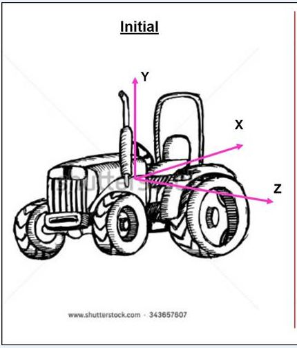
For my new project the required x y z coordinate directions should be like the below image.
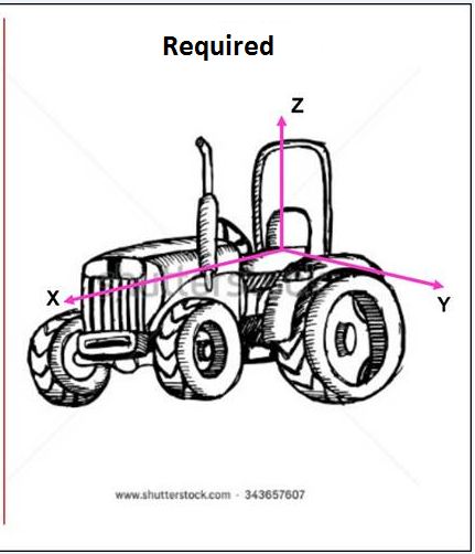
Can anyone suggest, How to create the "start part" with the required coordinate dirctions?
And we dont want to create new excess coordinate point.
I just tried and changed the view orienations with the existing xyz axes.
But it has problem with the creo viewer and illustrator assembly.
creo viewer shows the model invertible or reverse directions based on the previous
x y z directions.
Pls suggest how to create "start parts" with the required x y z axes and with out affecting the
view orientations and supporting to creo viewer.
Thanks in advance
uday
This thread is inactive and closed by the PTC Community Management Team. If you would like to provide a reply and re-open this thread, please notify the moderator and reference the thread. You may also use "Start a topic" button to ask a new question. Please be sure to include what version of the PTC product you are using so another community member knowledgeable about your version may be able to assist.