
13-Aquamarine
January 8, 2025
Solved

IFX fastener with custom geometry

  • January 8, 2025
  • 1 reply
  • 1843 views

I am looking for a way to create a fastener with _custom_ geometry, meaning that the screw should have geometric features that don't exist at all in any of the IFX screw types.

 In particular, I am currently looking for a way to create a captive screw that would have the geometry of DIN912 but a captive thread (rod).


See attached image - the existing dimensions in SCREWTYPE01 would remain, but additionally I would need a reduced-diameter rod size DC (to make it captive) , as well as full-diameter cylindrical face height DH (it may be slightly different from just a thread height B). I marked my new features and their sizes in red.


Is this possible in IFX? I would imagine, I may use any SCREWTYPE1 part as a starting point, modify the geometry, add two extra dimensions as required, adding control of these extra dimensions in the .dat file (i'd keep the "SCREWTYPE  1" in the .dat file) and hope it would work.


However before I try that myself I'd like to know if that sounds like it should work. I am worried that even if I manage to make it work, the IFX may be running some other code on the system level that im not aware of as a user, making this custom-geometry screw unstable, thus risking making our project files unstable later.


An easy way out would be to just use the a family table for captive screws, but having an option to easily add washers or easily switch between standard DIN912 and captive DIN912 is why i'm wondering if this is possible in IFX.


I am using Creo 9 and Windchill.
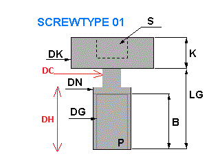
 

screw_01_detail.gif


@OliverGräbner  can you please advice? Thank you in advance!

Best answer by OliverGräbner

Hi @Ben8 


you can add your custom screw. This is no problem.


As base type you should use SCREWTYPE 01 and add a custom icon for this type which shows your captive screw.

NOTE: The preview (2D in Dialog and 3D in Creo) will only be displayed for the selected type.


All columns in the *.dat file are handeld in this priority:

  1. Search for an existing dimension with column name and set given value.
  2. Search for an existing parameter with column name and set given value.
  3. If either a dimension nor a parameter exist IFX create a new 'STRING' parameter with the name of the column and set given value.


Hope this helps.

If you need more details, please let me know.


1 reply

17-Peridot
January 8, 2025

Hi @Ben8 


you can add your custom screw. This is no problem.


As base type you should use SCREWTYPE 01 and add a custom icon for this type which shows your captive screw.

NOTE: The preview (2D in Dialog and 3D in Creo) will only be displayed for the selected type.


All columns in the *.dat file are handeld in this priority:

  1. Search for an existing dimension with column name and set given value.
  2. Search for an existing parameter with column name and set given value.
  3. If either a dimension nor a parameter exist IFX create a new 'STRING' parameter with the name of the column and set given value.


Hope this helps.

If you need more details, please let me know.


Ben813-AquamarineAuthor
13-Aquamarine
January 8, 2025

Thank you @OliverGräbner for assurance and your explanation, this is very helpful.

I even think this section should be written up as an article in Creo manual.


I will aim to build that screw now. In the meantime, could you let me know if feature names (not dimension names) are important and can they be changed? They seem to be named intentionally so I wonder how critical is it?


This is ScrewType01 prt model tree:

Feature_Names.jpg

Many thanks

17-Peridot
January 8, 2025

Hi Ben8,


you can rename the features like you want.

They are not important - only the dimension and parameter names are relevant.


In addition the Placement References (SURFACE, AXIS and ORIENT) can have names or you can use the geometry item id.
