
10-Marble
March 10, 2014
Solved

issue with assembling angular constraints

  • March 10, 2014
  • 1 reply
  • 3211 views

Hi all

I am working on a project at the moment that has two issues.

The first issue in this post.

I have created a turret assembly with 8 pockets, and have constraint it with axis & angular constraints.

and then using parameter & relations to set the position.

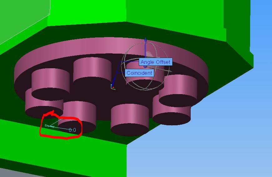
now this work fine with the first half of the turret up to 180 degrees
ZERO.JPG

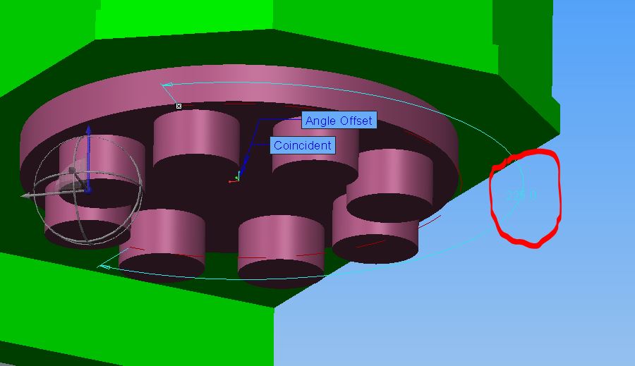
the pockets line up correct, but as soon as I pass 180 it reverts.
225.JPG

and the wrong pockets line up.

does any one know of a solution so I can rotate 360 degree.

Peter
Best answer by TomD.inPDX

True... it is very difficult to manage that one value in pin constraints.

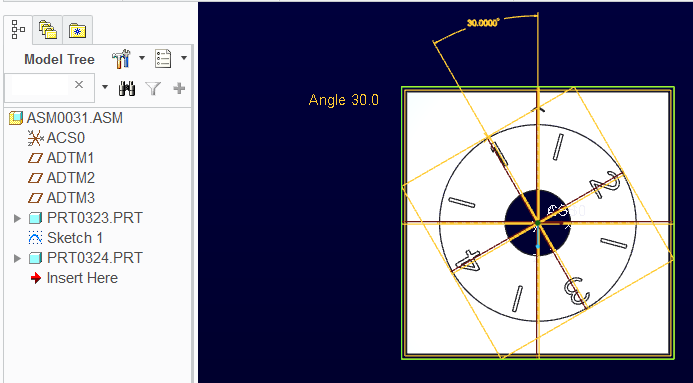
I have just created a file that does this correctly. It links an assembly sketch to the moving element.

The attached is Creo 2.0 full version.

Hold Alt>select-value-note"Angle nn.n>RMB>Value and change the angle value in the dialog. A value of zero will be converted to 360 internally.

turret_clocking_constraint.PNG

Have your annotation enabled. Regen required for the movement update.

The definition of ANGLE is a parameter but removed from relations so you can change it.

1 reply

17-Peridot
March 10, 2014

See if using a mechanism constrain might help. Use a pin and then try the same angle constraint and see if that doesn't behave better.

Pro|E has always been problematic about "reversals". You could ask customer service by opening a service ticket to see what they would recommend.

I might try a robust sketch to associate the turret to and see if it follows it better. Unfortunately, this is where fewer mouse clicks times number of attempts really makes the PTC mantra more like white noise.

10-Marble
March 10, 2014

I had tried to use a mechanism, but couldn't work out how to assign a parameter to the angle value, so I could created a relation to control its position.

I will try to use it just to see if this will resovle the 1st issue.

17-Peridot
March 10, 2014

True... it is very difficult to manage that one value in pin constraints.

I have just created a file that does this correctly. It links an assembly sketch to the moving element.

The attached is Creo 2.0 full version.

Hold Alt>select-value-note"Angle nn.n>RMB>Value and change the angle value in the dialog. A value of zero will be converted to 360 internally.

turret_clocking_constraint.PNG

Have your annotation enabled. Regen required for the movement update.

The definition of ANGLE is a parameter but removed from relations so you can change it.