
1-Visitor
December 23, 2016
Question

Modelling advice - cylindrical pv nozzle

  • December 23, 2016
  • 13 replies
  • 6314 views

Hello,

Just wondering if anyone had any advice as to how to go about modelling the cylindrical pressure vessel with nozzle shown below. It is changing in all 3 dimensions, so some kind of mixture of revolve and sweep seems logical. It is for a project so I will figure it out, just wondering if anyone has any helpful advice to save me getting lost.

Thanks
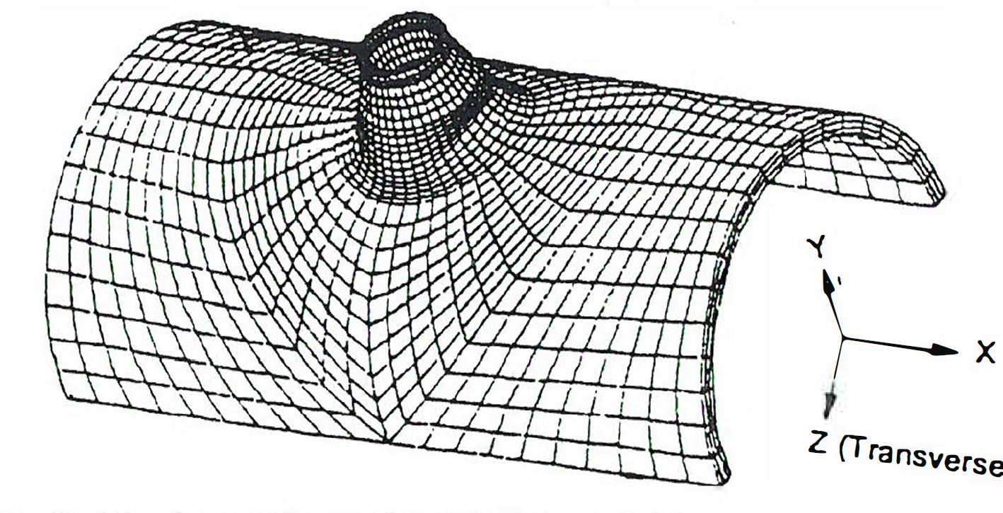
 

Cylindrical PV Nozzle.JPG

13 replies

rhamill1-VisitorAuthor
1-Visitor
December 30, 2016

Hello, I have made progress but have encountered some issues (which I think are related to the 'blended sweep' function in Creo 2.0).

I have several screenshots here: Pressure_Vessel_Nozzle by rhamill95 | Photobucket   [Photobucket link]. The picture titles give some detail as to what they are.

So far I have successfully created what I am fairly confident are the correct section geometries (was given details of these). I then inserted both sketches into one part file and created a 90 deg sketch (quarter circle) to be swept around. I have then used a 'swept blend' of surface one (with the curved wall) to the other around the line. I have also tried using the rotational blend feature which as expected gives the same result.

Swept_blend_standard.JPG

The problem I am having is that wall thickness is not uniform when it is swept. Therefore the pressure vessel would not have a constant wall thickness (as shown below) and I cannot extrude the main cylindrical body through. How can I get fix this issue and produce the geometry as shown in the original question? I have tried playing with the 'tangency' options as shown in the pictures in the link. Thanks for your help and I would really appreciate any replies!

Swept_blend_front_thickness_(1st_section_free)_with_cylinder.JPG

12-Amethyst
December 30, 2016

Your first picture looks like a half cylinder with a nozzle bonded into it.

The second post shows two sections both of which show the nozzle 'thickness' to be quite different than the main 'pressure vessel' geometry.

For constant thickness walls, I would recommend you use the offset or the shell tools. Perhaps break up the problem into modeling the overall vessel and the nozzle somewhat separately.

rhamill1-VisitorAuthor
1-Visitor
December 30, 2016

Thanks for the response!

The nozzle is incorporated into the cylinder. (I.e. the nozzle wall is thicker in parts however it then runs down into the cylinder so that it merges into the cylinder). The picture included at the end of my second post shows that it is almost right but if zoomed in on, the cylinder wall does not match the nozzle wall as it should. I hope that makes sense as it is difficult to explain!

1-Visitor
January 2, 2017

It's not my field of modeling. Anyway i made a quilt and then thickened (3mm). After this only one point wasn't 3 mm (thickness analysis). Someone expert of this can give a check.

Cattura.PNG

rhamill1-VisitorAuthor
1-Visitor
January 3, 2017

Thanks for your response! I had considered that initially however the model is not actually of uniform thickness (the nozzel thickness varies)! I am not sure if I have permission to upload my model but will find out and see. I am aiming for something like Antonius Dirriwachter has posted, so am hoping he can try to explain how he managed to achieve it and hopefully others can learn from this! Thanks, Robert