
8-Gravel
January 16, 2025
Question

Multibody Sheetmetal Information in drawing - Creo Parametric 11

  • January 16, 2025
  • 1 reply
  • 683 views

I want to start to use the multibody in the sheet metal. But I need first to implement this feature in my drawing. 

On my drawing all my drawing, I have a table with the Radius, thickness, K-factor, and a relation that calculate the Outside Bend allowance of my part. All this information is useful for the production. 
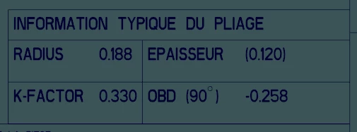
Current-Table.png

I have try with a test with 2 body, I have insert the body specific information &SMT_DFLT_BEND_RADIUS and &SMT_THICKNESS in the creation of my table, But it only take the base body information. I have also try to add this &SMT_BEND_ALLOWANCE_FACTOR, but the table does not accept this info. 

And if their a way to have a formula that change with each body to calculate the OBD for 90º of the part. 


My old way to give the information still work, but only for a single body, or for a multibody part that are all Body linked. 

1 reply

24-Ruby III
January 17, 2025

Hi,

following link is just for information ... I am not sure if it helps.

https://support.ptc.com/help/creo/creo_pma/r8.0/usascii/index.html#page/tutorials_pma/tutorial_7/mbtutorial7.html


Ratthy8-GravelAuthor
8-Gravel
January 17, 2025

Almost, the radius, thickness and bend allowance factor are a User Defined Symbol that you have to enter manually.

table-v1.png
My problem with, still, I cannot have my Bend Allowance factor with the correct information if it driven by material, I have to switch to be driven by parameter

parameters.png

My other problem that I have, Can we add a formula in this type of table? To calculate may ref OBD for 90º.


This type of table may be also use full if we can create Balloons with it. I have try, and it refuse to create balloons with this table. Found strange, because of the many body you can create with this, is still an assembly. It will be useful to be able to have balloons of each part (body).