Pattern relation question
- 8 replies
- 5658 views
- Translate All
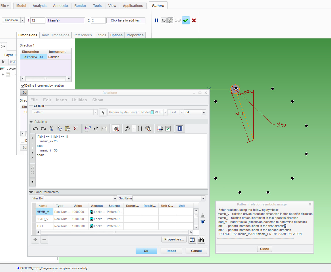
Trying to create my first patern relation and having a bit of a problem. I want to pattern a hole so that there are 12 instances total. The pattern will only be in one direction which is an angle. The first hole patterned I want it to be 25 degrees away from the first hole. The next 9 holes I want to be 30 degrees away from the 1st patterned hole. Then the last hole I want it to be 25 degrees away from the last hole. Please see the picture attached.
Now I know I could define each hole at a certain angle but I was wanting to do it a little more simpler. Below is what I have. But I don't think I fully understand how creo evaulates the relation which is why it isn't working.
increment1 = 0
if idx1 == 1 (first patterned hole, 25 degrees away from original hole)
memb_v = 25
endif
if idx1 >= 2 | idx1 <= 10 (patterned holes 2 through 10, 30 degress from each other)
memb_v = 30 + increment1
increment1 = 30 + increment1
endif
if idx1 == 11 (last hole patterened, 25 degrees away from last hole patterened)
memb_v = 25 - 30 + increment1
endif
So what I'm trying to do is use the "increment1" to keep increasing the angle by 30 degrees for patterened holes 2 though 10. And then the last hole only moves 25 degrees from the 2nd to last patterned hole.
"increment1" isn't defined as a paramenter. Not sure if this is necessary or not.
Any help is greatly appreciated!
This thread is inactive and closed by the PTC Community Management Team. If you would like to provide a reply and re-open this thread, please notify the moderator and reference the thread. You may also use "Start a topic" button to ask a new question. Please be sure to include what version of the PTC product you are using so another community member knowledgeable about your version may be able to assist.