
1-Visitor
December 10, 2021
Question

Patterning Rounds Feature

  • December 10, 2021
  • 15 replies
  • 6639 views

New Creo 5.0.4 user


I have a hole pattern and created some access cuts on a sheet metal part (see picture below).  I rounded/filleted the edges (highlighted in green).  The cut feature patterned easy enough following the hole pattern, but I cannot pattern the rounds (greyed out).
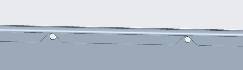
 

Capture.PNG


Outside of adding the fillets to the cutout sketch, is there a way to pattern this?  Selecting all of the patterned edges for the round feature seems tedious, and I would guess there would be issues if the hole quantity changed.


Thanks,

Greg

15 replies

StephenW
23-Emerald III
December 10, 2021

I don't know about this specific use case but if I want to pattern rounds with features, I typically will get one area done completely, group those features, then pattern the group.

Greg_H1-VisitorAuthor
1-Visitor
December 10, 2021

I was excited to try out your solution, but unfortunately I got regeneration errors.  I tried grouping the round with the cut 1st, and then I removed the original hole pattern and tried grouping all 3 features in 1 pattern, same error.  ☹️

tbraxton
22-Sapphire II
December 10, 2021

Grouping will work in most cases like this as @StephenW  posted. The most likely issue is that your references are being lost when patterning. Without inspecting the features, it is hard to tell. If you post the model or a similar one with your grouping of the features someone may be able to troubleshoot it.


I have posted a model for reference (Creo 4) that utilizes a pattern scheme similar to what you want. In this test case a group is not used intentionally for debugging purposes. So you will see 3 patterns rather than one pattern of a group. Sometimes this is necessary depending on the references needed and reference patterns are used for the subsequent patterns.


It is also using intent references, but it should give you an idea of how to handle your design intent. The intent refs are used to make the pattern much more flexible so it will turn the corner on the shape. You can demonstrate this by increasing the # of instances in pattern 1 from 5 to 6 instances.

StephenW
23-Emerald III
December 10, 2021

Creo 4

I  just did it and didn't have any problems without a group and again with the group.

changed pattern qtys and it all just worked fine.

If you can, attach a file.

StephenWilliams_0-1639167077395.png

StephenWilliams_1-1639167144495.png


Greg_H1-VisitorAuthor
1-Visitor
December 10, 2021

I'm attaching the model.  I've eliminated the features that were not relevant to this issue.  I think the issue is the double mirror.  As I said, I have other cut outs and tabs not shown in the attached.  I'd rather mirror the body than collection of features, but maybe that isn't the creo way?


Thank for your time. 


(edit: I screwed up the holes removing features, I'll repost model in a few minutes)

(edit2: ok, here's the fixed model that is having the specific topic issue)

CREO 5

tbraxton
22-Sapphire II
December 10, 2021

As I had suspected the round edge references are failing in your model. The issue is with the intent edges of the rounds (.125 R) on the cut. In your part, the intent edges as defined internally by Creo are not playing nicely with the pattern. You have no direct control over that. Sheetmetal parts have historically not been compatible with core modeling features in some cases.


I have posted a part that does pattern the geometry as you desire and uses the mirror of the geometry as you intend. I created a solid part and then converted it to sheet metal. This represents one way to generate the model with the geometry and pattern you specified. I hacked this together fast to test it.


The model is Creo 7. Model tree shown in case you don't have Creo 7.


Feature TreeFeature Tree